Analog output, External clock input, Digital i/o – Measurement Computing BTH-1208LS-OEM User Manual
Page 15: External pull-up/pull-down capability
BTH-1208LS-OEM User's Guide
Functional Details
15
Carefully match the gain to the expected voltage range on the associated channel or an over range condition
may occur. Although this condition does not damage the device, it does produce a useless full-scale reading,
and can introduce a long recovery time due to saturation of the input channel.
Analog output
Two 12-bit analog outputs are available at
AOUT0
and
AOUT1
on connector J1.
Each analog output channel has an output range of 0 V to 2.5 V. Throughput is system-dependent.
The D/A is software paced.
External clock input
The BTH-1208LS-OEM provides one external clock input for the analog input pacer. You can connect an
external clock signal to
AICKI
on connector J2.
Digital I/O
You can connect up to eight digital I/O lines to
DIO0
through
DIO7
. The digital I/O terminals can detect the
state of any TTL-level input.
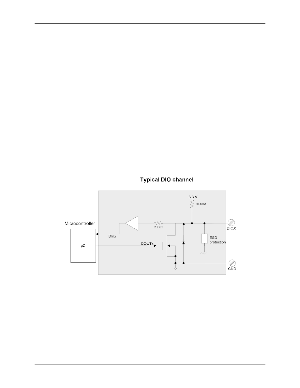
Digital input voltage ranges of up to 0 to 5.5 V are permitted, with thresholds of 0.8 V (low) and 2.0 V (high).
Each DIO channel is an open-drain, which can sink up to 50 mA for direct drive applications when used as an
output.
Figure 3 shows an example of a typical DIO connection. The figure represents connections for one channel. The
other seven channels are connected in the same manner.
Figure 3. Digital output connection example
External pull-up/pull-down capability
Inputs are pulled high by default to 3.3 V through 47.5
kΩ resistors on the circuit board. The pull-up voltage is
common to all 47.5
kΩ resistors.
You can place an external pull-up resistor on any of the DIO bits in order to limit source current to less than 50
mA., which requires a 100
Ω resistor minimum. A 2 kΩ or 5 kΩ resistor would be typically used, allowing for a
1 mA current
You can also use an external pull-up resistor to pull the DIO bit up to a voltage that exceeds the internal 3.3 V
pull-up voltage (5.5 V maximum).
When using external pull-up resistors, be aware that the internal resistors cause a slight voltage shift to digital
lines in the on state as various lines change between the on/off states.