Cab controls (analog), Cab controls (analog) -3, System description – MEGA Corp. MSC-OPS-1 User Manual
Page 12
MSC/MST-OPS-1
31 Dec 2013
SECTION 2
System Description
2-3
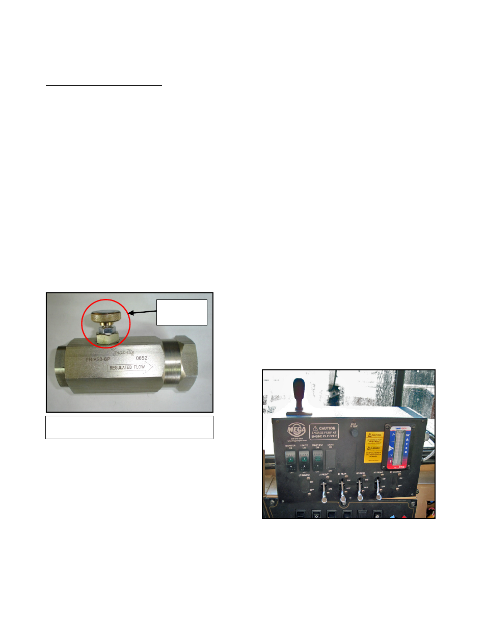
Hydraulic Flow Control Valve
The hydraulic flow control is directional. The arrow on
the body indicates the direction of oil flow to meter
the bypassing oil. The adjusting knob on the valve
will allow adjustment of the oil flow to bypass the
drive motor, up to135 LPM (35 GPM) or up to 700
RPMs (RPM increase/decrease will vary depending on
the size of hydraulic drive motor the unit is equipped
with). If the flow control is reversed, the flow control
adjusting knob will not function and the full flow
capacity of the valve will bypass. This can result in
water pump rpm being below specifications with no
adjustment capability of the adjusting knob. By
turning the adjusting knob clockwise the hydraulic
oil that is bypassing will be reduced, increasing the
speed of the water pump. Turning the knob counter-
clockwise will increase the volume oil being
bypassed reducing the water pump speed. The flow
control valve is typically mounted on the PRESSURE
manifold of the hydraulic drive motor.
HYDRAULIC DRIVE MOTOR ACTIVATION
The hydraulic drive motor on MSC/MST's are typically
driven by the chassis implement hydraulic system.
The activation can be controlled by the following;
Pilot Operated Diversion Valve - A remote
mounted diversion valve that receives an electric
signal from the cab control pump switch to activate a
pilot control to move a spool within the diversion
valve redirecting the hydraulic oil to flow to the water
pump drive motor. Typically this type of valve is
installed between the hoist pump and the hoist
valve.
Existing Mechanically Operated Implement
Valve - Typically used on early model trucks with a
pneumatic system. This system is operated by the
existing cab control lever. When the lever is moved
to move a spool valve which divert hydraulic oil to
the water pump drive motor.
CAB CONTROLS (ANALOG)
MSC/MST units can be configured with a manual
pneumatic, electro-pneumatic or electro-hydraulic
control system.
MANUAL PNEUMATIC
Multi-function control box mounted in the cab to
control all water tank functions. Spray system head
and auxiliary functions are controlled by using
manual pneumatic levers, accessory switches and
embedded joystick. The cab control requires 24 VDC
power to operate.
Typical 135 lpm (35 gpm) Adjustable
Hydraulic Flow Control
ADJUSTING
KNOB