Hydraulic drive motor, Hydraulic drive motor -2, System description – MEGA Corp. MSC-OPS-1 User Manual
Page 11: Msc/mst-ops-1
MSC/MST-OPS-1
31 Dec 2013
SECTION 2
System Description
2-2
3. Wear Ring – Acts as a bearing surface between
the impeller and volute case. Constructed of
bronze material.
4. Impeller – Rotating wheel attached to the shaft
that accelerates the speed of the water producing
water flow and pressure.
5. Shaft Seal – Confines grease to the inner and
outer bearing area while keeping foreign material
from entering the bearing area and seals water
inside the volute case.
6. Rope Seal – Provides a seal around the rotating
pump shaft at the volute case. Constructed of a
graphite rope material that is designed to drip
water and allow shaft lubrication.
7. Upper/Lower Bearings - Provide roller surface
for the pump shaft.
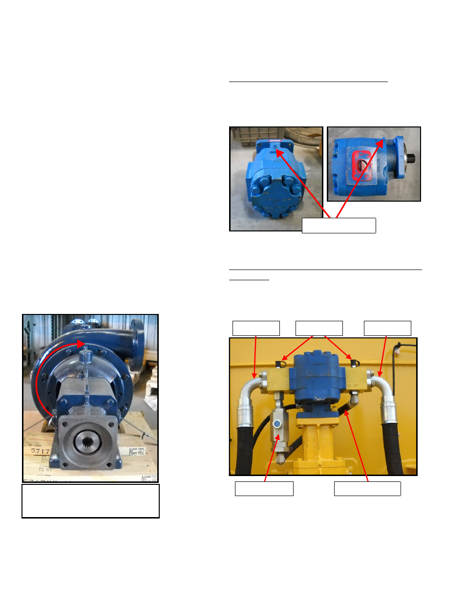
HYDRAULIC DRIVE MOTOR
M-4 PUMP DRIVE MOTOR AND CROSSOVER
ASSEMBLY
The M-4 pump rotates clockwise as viewed from the
drive end of the assembly.
The hydraulic drive motor may be installed in 4
different orientations depending on the water pump
location or application.
Hydraulic Drive Motor Port Identification
The hydraulic drive motor requires hydraulic flow
from a valve to the motor pressure port, return oil
flow to the hydraulic reservoir and a free to tank case
drain.
Hydraulic Drive Motor Speed Control (Crossover
Assembly)
The hydraulic drive motor speed control (Crossover
Assembly) consists of a flow control valve, 2 hydraulic
manifolds, crossover hose and test ports.
Clockwise rotation as viewed from
the drive end of the water pump
assembly.
CASE DRAIN PORT
PRESSURE
RETURN
TEST PORTS
FLOW CONTROL
CROSSOVER HOSE