System description – MEGA Corp. MMP4-1 User Manual
Page 11
MMP4(T2)-OPS-1
4 Oct 2011
SECTION 2
System Description
Contents
2-1
MMP4 Description and Usage
…………
2-1
MMP4 Frame …………………………… 2-1
Hydraulics ……………………………….. 2-1
Axial Water Pump ………………………. 2-2
Engine Control Box ……………………... 2-2
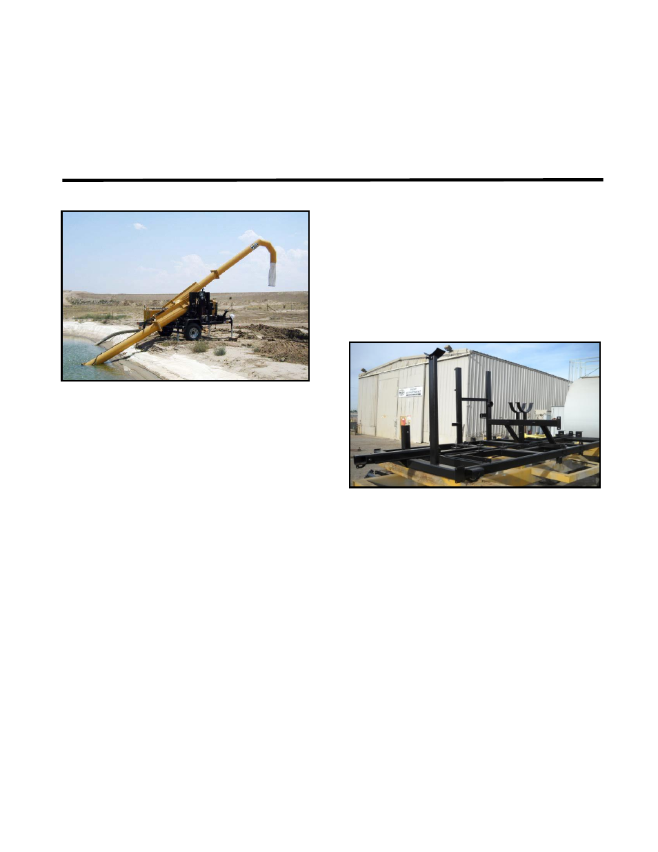
MMP4 DESCRIPTION AND USAGE
The MMP4 is designed to be towed behind a
typical ¾ ton or 1 ton capacity pickup truck.
The MMP4 can be transported over the road to
just about any water holding pond area used for
filling water distribution equipment.
The MMP4 can be set up, made ready for
operation and reconfigured for transport by 1
person and simple hand tools. The MMP4’s
primary usage is to lift water from a water
holding pond and discharge the water into the
fill port on water haulage equipment. The
MMP4 is equipped with a Diesel engine with
an integrated hydraulic pump and oil cooler, 50
gallon (190 liter) diesel fuel tank, 32 gallon (87
liter) hydraulic oil reservoir, 3 circuit hydraulic
control valve, DOT rated lighting, 6,000 pound
(2,725 kg) capacity axle and tire combination, 3
point stabilizing jacking system, hydraulically
operated inlet and discharge boos, 12” axial
hydraulic drive water pump and a folding hitch
assembly. The MMP4 is capable of lifting
water approximately 25’ (7.62 meters) with a
discharge port approximately 17’ (5.2 meters)
above ground level.
MMP4 FRAME
The MMP4 frame is the back bone of the unit,
manufactured
using
rectangular
tubing.
Attached to the frame is the 6,000 lbs (2,725
kg) capacity axle assembly, boom supporting
structures, hydraulic and fuel tanks, engine
assembly including a battery and tool storage
box, a fold away hitch assembly, rear walk
way, fenders and DOT rated lighting.
HYDRAULICS
The hydraulic system of the MMP4 consists of
an engine mounted hydraulic pump, 35 gallon
(135 liter) hydraulic oil tank equipped with an
inlet screen, return oil diffuser, external shut off
valve, oil level sight glass and a breather
equipped filler cap. The balance of the
hydraulic system is designed with a 10 micron
rated return oil filter, 3 spool hydraulic control
valve with pressure regulation capability, a
hydraulic oil cooler equipped with a bypass
valve to protect against hydraulic shock when
the oil is cold, hydraulically driven submergible
12” axial water pump, hydraulic cylinders to
lift the inlet and discharge booms.