LSC Lighting EKO User Manual
Page 16
EKO Dimmer Installation
EKO Dimmer
Operator Manual V2.3
Page 12
LSC Lighting Systems (Aust) Pty. Ltd
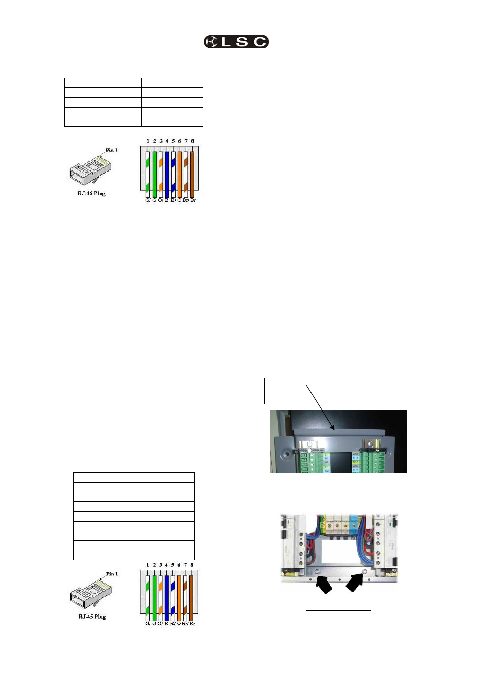
DMX RJ45 Pin Numbers
RJ45 Pin Number
DMX512
1 DMX
+
2 DMX
-
3,4,5 & 6
Not Used
7 & 8
DMX Common
The end of the DMX line must be terminated. A
DMX Terminator switch is located on the
Installation Frame “Control Connector Board”.
If the DMX line is looped out from an EKO
dimmer to another EKO or other DMX
equipment, then the termination switch must be
set to the UNTERM position.
If the DMX line is NOT looped out from an EKO
dimmer, then the termination switch must be set
to the TERM position.
4.4.4.2 CONNECTING LSCNET TO
THE INSTALLATION FRAME
The EKO dimmer can be remotely controlled
from LSC ePlates via the LSCnet.
Connection between devices on the LSCnet is
via RJ45 connectors using CAT5 cable. The
cable is run in a daisy chain that loops from
device to device. The cable carries both data
and power. The maximum total length of the
cable is 800 metres. If longer cable runs are
required, a data repeater must be used to
regenerate the data. Contact your LSC agent for
details on data repeaters.
LSCnet RJ45 Pin Numbers
Pin Number LSCnet Function
1 Spare
2 Spare
3 LSC
Net
+
4 PSU
+
5 PSU
+
6
LSC Net -
7 PSU
-
8 PSU
-
Each device on the LSCnet has two RJ45
sockets allowing the LSCnet cable to be looped
from device to device. It is essential for correct
network operation that the first and last device
in the network be terminated and that all other
devices are not terminated. See section 5.4
LSCnet Cabling
for more details.
If an EKO dimmer or ePlate has both of its
RJ45
sockets connected to the LSCnet then the
termination switch on that device must be set to
UNTERM
.
If an EKO dimmer or ePlate has only one of its
RJ45
sockets connected to the LSCnet then the
termination switch on that device must be set to
TERM
.
The first stage of the installation process is
now complete.
4.5 STAGE 2.
INSTALLING THE EKO DIMMER CABINET
4.5.1 Hanging the Dimmer Cabinet on
the Installation Frame
When the load and control circuits have been
connected to the Installation Frame, the EKO
Dimmer cabinet can be hung on the Installation
Frame.
Remove the two ny-lock nuts from the bottom of
the Installation Frame and put them aside. Pick
up the Dimmer Cabinet and hang it on the
hanging lip at the top of the Installation Frame.
Secure the Dimmer Cabinet to the bottom of the
Installation Frame using the two “ny-lock” nuts
that were previously removed.
Hanging
Lip
Ny-lock Nuts