2 connecting to the refractometer system, Fc-11 field communicator instruction manual, Connector in the dtr – K-Patents FC-11 User Manual
Page 8
4
FC-11 Field Communicator instruction manual
Document/Revision No. Rev. 1.0
Effective: January 15, 2014
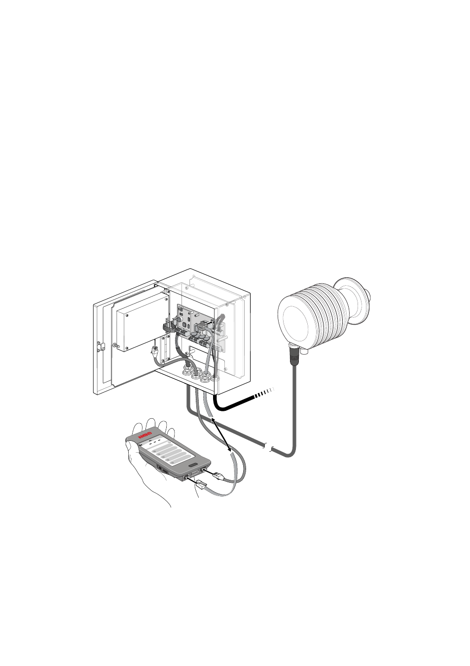
2 Connecting to the refractometer system
The FC-11 Field communicator can be connected and disconnected without shutting down either
the refractometer system or the communicator.
2.1 Connecting to an Indicating transmitter DTR / a PR-23 system
The connection is made with a standard ethernet cable. One end of the cable is plugged into
your transmitter’s ethernet output, the other end goes into the FC-11.
The power adapter PR-8811 is connected to (3) on the handset and to the
EXTENSION
connector
in the DTR.
DIA
GNOSTI
CS
MEA
SURMENT
TOOLS
DATA LOGGING
SETTINGS
MA
IN MEN
U
nD
1.37924
NOR
MAL
OPER
ATION
27
.36°C
23.
15
172.16.23.108
PR-33-
AC
R09690
x
SETTINGS
DEVICE INFO
TOOLS
DIAGNOSTICS
MEASUREMENT
A
172.16.23.182
95%
nD
1.3818
NO
RM
AL
OPER
ATIO
N
2
7.5°C
MAIN MENU
?
Figure 2.1
Connecting FC-11 to a DTR
Note:
The FC-11 fits inside the PR-23 Indicating Transmitter enclosure even when connected
and can be left in the DTR e.g. to log data.