Operation disturbances, Accessories – Kemppi DC 3500W User Manual
Page 19
9901 / 1916110E / 19
English
6.2 Cables
Check the condition of the welding and connection
cables daily. Do not use damaged cables!
Check also that the mains connection cables that you
use are in good condition and that they comply with all
the regulations!
Mains connection cables may be repaired and installed
only by an authorized electric shop or electrician.
6.3 The power source
NOTE! Disconnect the plug of the machine from the
mains socket and wait for ca. 2 minutes (capacitor
charge) before removing the casing plate.
Check at least very six months:
The electric connections of the machine clean any
oxidized parts and tighten any loose ones.
NOTE! You must know the correct tension torques
before you start to repair the connections.
Clean the inner parts of the machine from dust and
dirt e.g. with a soft brush and a vacuum-cleaner.
Do not use pressurized air, because there is the
danger that the dirt is packed even more tightly in
the gaps of the cooling profiles. Do not use a pres-
sure washing device.
Only an authorized electric shop or electrician may re-
pair the machine.
6.4 Regular maintenance
KEMPPI Service Repair Shops handle regular mainte-
nance by agreement.
Regular maintenance includes e.g. the following:
Cleaning of the machine.
Checking and maintenance of the welding tools.
Checking the clamps, switches and potentiome-
ters.
Checking the electric connections.
Checking the mains cable and plug.
Replacement of any parts that are damaged or in
poor condition.
Maintenance testing. The operation and perform-
ance values of the machine are checked and,
where necessary, adjusted by means of test equip-
ment.
7. OPERATION DISTURBANCES
In the case of operation disturbances, contact an au-
thorized KEMPPI Service Repair Shop.
Check the maintenance parts before sending the ma-
chine to the service shop.
8. ACCESSORIES
8.1 Remote control units
C 100C
Control of MMA / TIG welding current, memory scale
1 - 10.
C 100D
Control and fine-tuning of MMA / TIG welding current,
memory scale 1 - 10.
C 100AC
Control of MMA / TIG welding current, memory scale
1 - 10 and MMA / TIG selection.
C 100F
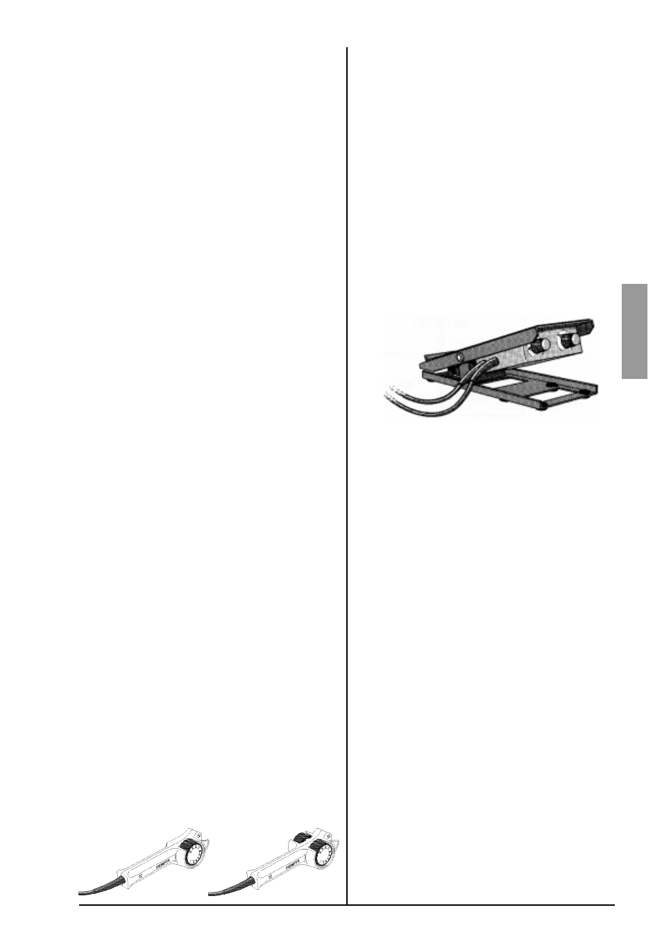
Foot pedal control unit for TIG welding
start function
adjustment of the welding current with pedal move-
ments
limitation of the welding-current range with min and
max potentiometers
Connecting the foot pedal unit
:
The foot pedal unit has two connections, which are
connected to the remote control and start connections
in the rear of the power source. When using the foot
pedal unit, the maximum current output of the machine
is ca. 30 % below its maximum output unless the ma-
chine is calibrated for the foot pedal unit.
Calibration of the machine for the foot pedal unit:
1. Turn the machine off.
2. Press the REMOTE key and at the same time turn
the machine on; the display will show the text rEn 01.
3. Turn the current adjustment knob so that the dis-
play will show rEn 02. (01=C 100C, 02=C 100F)
4. Press the REMOTE key so that the setting is saved
in the memory.
C 100C
C 100D
C 100AC