Installation, Assembly of mig system – Kemppi Promig 200 User Manual
Page 9
PROMIG 200, PROMIG 300 / 0537 – 9
© KEMPPI OY
Promig 300
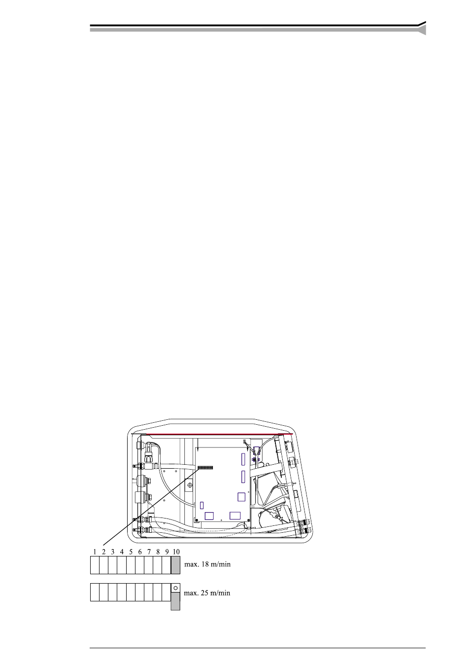
JUMPER
BLOCK
2. INSTALLATION
2.1. ASSEMBLY OF MIG SYSTEM
Assemble the units in below-mentioned order and follow mounting and operation instructions
which are delivered in packages.
2.1.1. Installation of power source
Read paragraph: ”installation” in operation instructions 1913130E for PRO power sources and
carry out the installation according to that.
2.1.2. Mounting of PRO power source to transport unit
P40 6185264,
air-cooled MIG system
P40L 6185264L
P30W 6185262, liquid-cooled MIG system
2.1.3. Connecting cables
Connect cables according to figures on pages 5-6.
Air-cooled system on page 5. Liquid-cooled system on page 5.
Promig 300 sub-feeders on page 6.
You can change polarity of filler wire by interchanging the Promig welding current cable and
earth cable with welding cable connectors from PRO power source.
2.1.4. Max. wire feed speed (Promig 300)
When the unit is delivered the max. wire feed speed is 18 m/min, which is enough for most
welding aplications. If you need a higher speed, you can increase the max. wire feed speed to
25 m/in min by replacing the gear wheel on motor shaft to a bigger one. The big gear wheel D40
is delivered only with the feed unit Promig 300.