Installation of mig system – Kemppi Promig 200 User Manual
Page 10
10 – PROMIG 200, PROMIG 300 / 0537
© KEMPPI OY
When necessary speed is changed according to following:
- Open side plate and move jumper block’s 10th jumper on control card A001 to point
25 m/min.
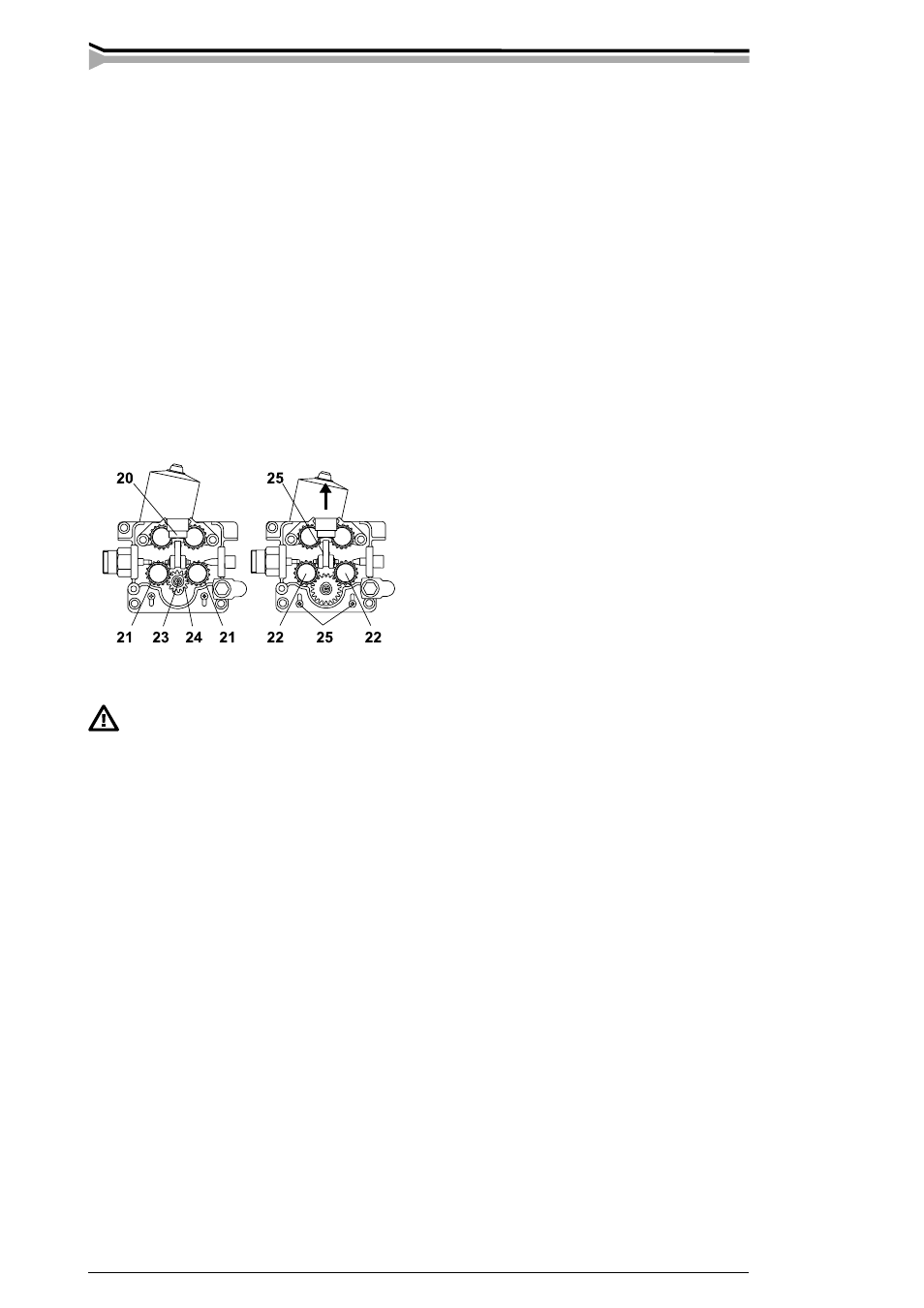
- Open tightening lever (20). Remove lower feed rolls (21). Release screw (23) and its washer.
Remove gear wheel D28 (24) from motor shaft.
- Loosen screws (25) (3 pc) 1 twist. Mount the D40 gear wheel onto motor shaft. Screw the
screw (23) with its washer back.
- Put feed rolls (21) back to their axles, however don’t fasten yet fastening screws of feed
rolls (22).
- Lift the motor so that the gear tooth gap between gear wheel and both lower feed rolls is
approx. 0,2 mm.
- Tighten screws (25). Check gear teeth gaps, when necessary put the motor into a better
position. Screw on the mounting screws of feed rolls (22).
NOTE! Too small gap between gear wheel and feed rolls will overload motor. Too big gap for its
part might cause too rapid wearing for teeth of feed rolls and gear wheel.
2.1.5. Mounting of Promig 200, 300 to boom
Wire unit must be mounted to boom in such a way that its chassis is galvanised
separated both from swing arm and boom.
For boom hanging you get with Promig 300 delivery plastic grip (is mounted onto rear plate of
the unit) as well as metallic suspension hook.
2.2. INSTALLATION OF MIG SYSTEM
2.2.1. Accessories corresponding to wire diameter
Promig wire feed rolls are available with plain groove, knurled groove and with U groove for
different purposes.
Feed rolls with plain groove: Universal feed roll for welding of all kinds of wires.
Feed rolls with knurled groove: Special feed roll for cored wires and steel wires.
Feed rolls with U groove:
Special feed roll for aluminium wires.
Promig wire feed rolls have two grooves for different filler wire diameters. Correct wire groove
is selected by moving selecting washer (28) from one side to another in feed roll.
colour ....................... filler wire ø mm (inch)
white ......................... 0,6 and 0,8 (0,030)
red ............................ 0,9/1,0 and 1,2 (0,035, 0,045 and 0,052)
yellow ....................... 1,4, 1,6 and 2,0 (1/16 and 5/64)
black ......................... 2,4 (3/32)
colour ....................... filler wire ø mm (inch)
orange ...................... 0,6-1,6 (0,024-1/16)
blue ........................... over 1,6 (over 1/16)