Operational functions, Main switch s14, Welding method selecting switch s15 – Kemppi Promig 200 User Manual
Page 15: Control mode selecting switch s16
PROMIG 200, PROMIG 300 / 0537 – 15
© KEMPPI OY
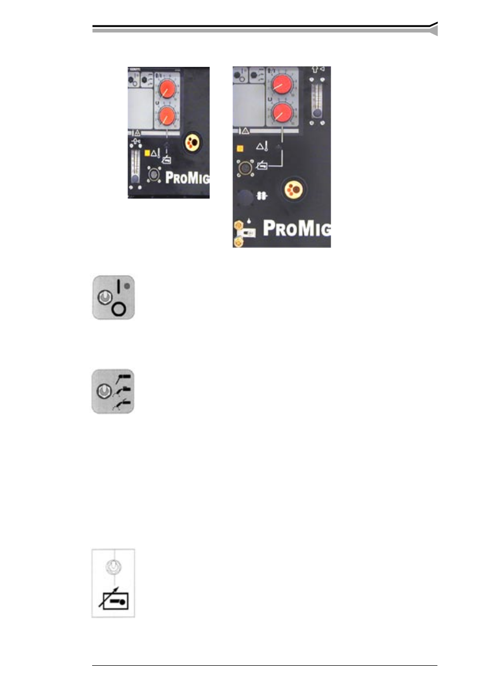
3. OPERATIONAL FUNCTIONS
3.1. MAIN SWITCH S14
Position I
Unit is ready for welding and this is indicated by green pilot lamp H13.
Position O
MIG/MAG welding: operations are arrested, power source and wire feed motor
don’t start and solenoid valve for gas is not opened though start switch of gun
is pressed down. Wire drive switch S11 for filler wire needed by reel change is
operating. MMA welding: Operations are arrested, welding circuit is dead.
3.2. WELDING METHOD SELECTING SWITCH S15
MMA
MMA welding with stepless welding current control
MIG two-sequence procedure (normal function)
MIG/MAG welding with two-sequence procedure of welding gun start switch
1. switch pressed: welding starts
2. switch released: welding stops
MIG four-sequence procedure (hold switch)
MIG/MAG welding with four-sequence procedure of welding gun start switch
1. switch pressed: shielding gas flow starts
2. switch released: welding starts
3. switch pressed: welding stops
4. switch released: shielding gas flow stops
Local control:
Control potentiometers R11 and R12 on panel are used.
Remote control:
Adjustments are carried out from remote control unit which is connected to remote
control connector X11 of wire feed unit. See operations of remote control units
R20 and R10 on page 18.
NOTE! If the remote control unit is not connected to the Promig unit and you have
selected remote control, controls operate with local control potentiometers like in
local control position.
3.3. CONTROL MODE SELECTING SWITCH S16