JIMS Box 2 1208-1352 (all models of 120, 131, or 135 Alpha, Beta and Evo Mount Engines) User Manual
Page 15
555 Dawson Drive, Camarillo, CA 93012 Phone 805-482-6913 • Fax 805-482-7422
14
Rev I
8-12
No.1208-1352
A Division of Thiessen Products, INC
IIn
ns
st
tr
ru
uc
ct
tiio
on
n S
Sh
he
ee
et
t F
Fo
or
r B
Bo
ox
x 2
2 1
12
20
0”
”,, 1
13
31
1”
” o
or
r 1
13
35
5”
”
E
En
ng
giin
ne
e A
As
ss
se
em
mb
bl
liie
es
s O
Or
r E
En
ng
giin
ne
e R
Ra
ac
ce
e K
Kiit
ts
s
• Of course the fins should also be straight and undamaged.
• Any small chipped paint areas can be touched up later.
• Inspect the head gaskets. See Fig. 60.
• They should be smooth and clean.
• A small amount of curl is okay.
• The surface coating should be intact.
• You will find a small area of machined fins on the spark plug side of each
head, as pictured. This is normal. See Fig. 59
Head Gasket Installation
VERY IMPORTANT NOTES:
• The head gaskets can be installed either of two ways; only one is cor-
rect.
• Incorrect installation will close-off the oil drain hole from the head.
• Incorrect head gasket installation requires a partial engine tear-down to
fix.
Head Gasket Orientation:
• The gaskets have a seventh hole about 3/8” in diameter, near one of the
stud holes.
•
Install each gasket so this hole is over the oil drain hole in its cylinder.
See Fig. 60.
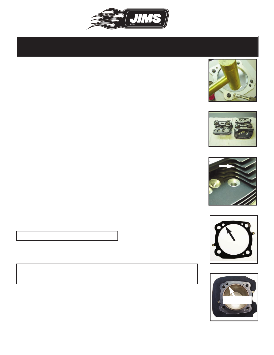
• The front cylinder’s drain hole is located at the left-front. See Fig. 61
• The rear cylinder’s drain hole is located at the left-rear. See Fig. 62
• Make sure each cylinder and gasket is clean, and free of oil.
•
Place the gasket over the locating dowels (Dry).
Note: Do not apply sealant to gasket.
• Double check to make sure the oil drain hole in the gasket aligns with
the oil drain hole in the cylinder.
Note: The JIMS 120, 131 or 135 Race Kit gaskets do not need or use O-rings.
The gasket coating and embossment seals the surfaces and eliminates
oil leaks.
Cylinder Head Installation
•
Clean the head gasket sealing surface with a lint free cloth and dena-
tured/ isopropyl alcohol and allow the surface to dry prior to installation.
•
Lightly lubricate, with the supplied moly lube, the threads of the cylin-
der studs.
Fig.57 - Gently tap dowel pin
Fig.58 - Inspect heads
Fig.59 - Paint machined fins
Fig.60 - Note oil hole
Fig.61 - Note oil hole
Drain Hole
Drain Hole