JIMS Box 2 1208-1352 (all models of 120, 131, or 135 Alpha, Beta and Evo Mount Engines) User Manual
Page 12
555 Dawson Drive, Camarillo, CA 93012 Phone 805-482-6913 • Fax 805-482-7422
11
Rev I
8-12
No.1208-1352
A Division of Thiessen Products, INC
IIn
ns
st
tr
ru
uc
ct
tiio
on
n S
Sh
he
ee
et
t F
Fo
or
r B
Bo
ox
x 2
2 1
12
20
0”
”,, 1
13
31
1”
” o
or
r 1
13
35
5”
”
E
En
ng
giin
ne
e A
As
ss
se
em
mb
bl
liie
es
s O
Or
r E
En
ng
giin
ne
e R
Ra
ac
ce
e K
Kiit
ts
s
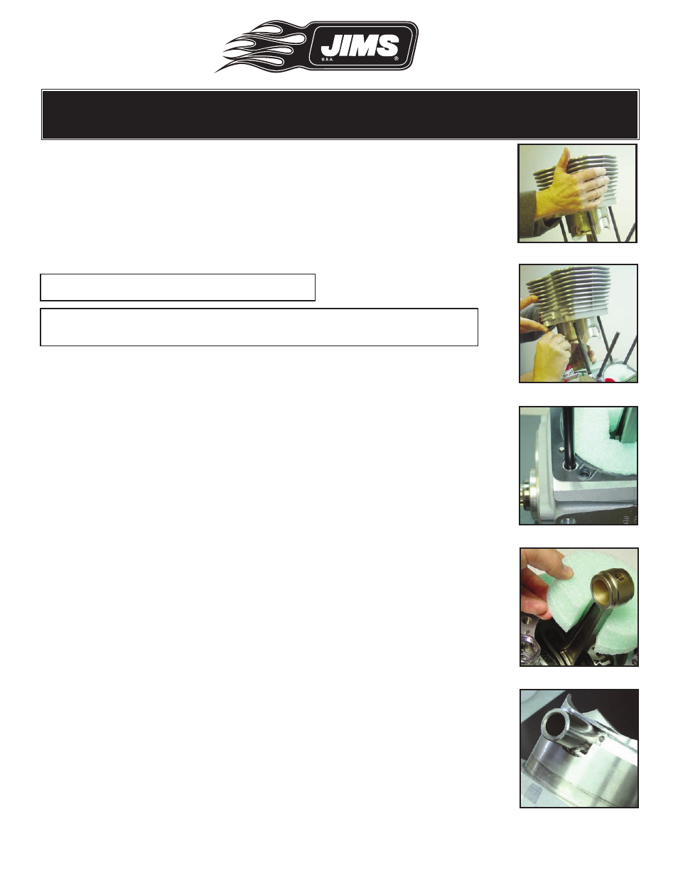
• Work from the right side of the short block.
• One person should hold and position each piston/cylinder assembly.See
Fig. 42
• The second can then align the connecting rod with the wrist pin and
insert the pin into the rod. See Fig. 43
• Uncover the short block and position it with room to work comfortably.
• Make sure the cylinder base gaskets are properly positioned.
Note: Do not apply any sealant to gasket.
Note: Oil return hole position in case, make sure it lines up with the base
gasket, as pictured. See Fig. 44.
• If you are using the recommended JIMS No.1022 Alpha , or No.902
Beta Twin Cam Engine Stand, or a similar stand, we recommend you
bolt it down before proceeding. The engine is going to get taller and
heavier and needs to be secured.
• Carefully shield the crankcase so foreign objects, like a dropped piston
pin clip, cannot fall into the engine.
• You can slit and re-install the original foam shields JIMS used to hold
and isolate the rods. This technique centers the connecting rod and
makes cylinder installation a bit easier. See Fig. 45
• Other materials such as clean lint free towels can also be used.
Installation: Rear Cylinder
• Lay the rear piston/cylinder assembly on its side.
• With the small spigot cutaway up. Rotate the piston so the wrist pin
hole aligns with the cutaway. See Fig. 46.
• Gently push the piston down the bore until the pin hole is exposed
enough to receive the pin.
• Pre-lubricate the piston’s wrist pin hole by inserting a lubed wrist pin
with assembly lube into the pin hole. Slide the wrist pin in until it bot-
toms out on the left side wrist pin clip, and then remove the wrist pin.
See Fig. 46.
• Rotate the crankshaft until the rear connecting rod is at the top of its
travel (TDC).
Fig.43 - Insert wrist pin
Fig.42 - Assistant holds assy.
Fig.44 - Oil hole aligned
Fig.45 - Use foam support
Fig.46 - Lube wrist pin