Connection to a profibus network, 3 connection to a profibus network – Datalogic Scanning C-BOX 300 User Manual
Page 25
INSTALLATION
2
9-pin external female connector pinout
Pin Name
Function
1 N.C.
not
connected
2 N.C.
not
connected
3 B-LINE
(RS485+)
4 RTS
Ready
To
Send
5
GND
RS485 Bus Reference
6
+ 5V (galvanically isolated)
RS485 Bus Power Supply
7 N.C.
not
connected
8 A-Line
(RS485-)
9 N.C.
not
connected
2.5.3
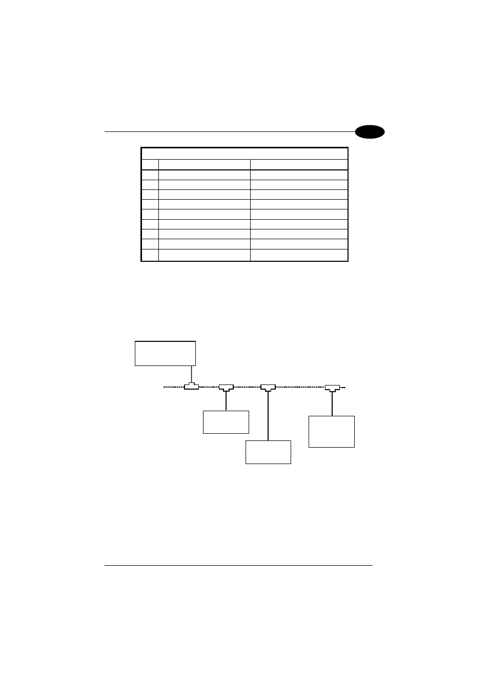
Connection to a Profibus Network
The following figure shows a Profibus layout with C-BOX 3X0 devices connected to a
Profibus Master:
Profibus DP
Slave node #1
PROFIBUS DP
Master
Profibus DP
Slave node #2
Profibus DP
Slave node #n
C-BOX 3X0
Figure 12 - Profibus Connection
It is recommended to use only commercially available PROFIBUS connectors for
connecting to the bus. Use connectors from ERNI and Siemens. If the C-BOX is
installed at the beginning or end of the PROFIBUS cable segment, it is
recommended to use PROFIBUS connectors, which contain an integrated
terminating resistor.
13