Motherboard internal diagram --for nmf95-h81 – Jetway Computer NMF95-Q87 User Manual
Page 7
3
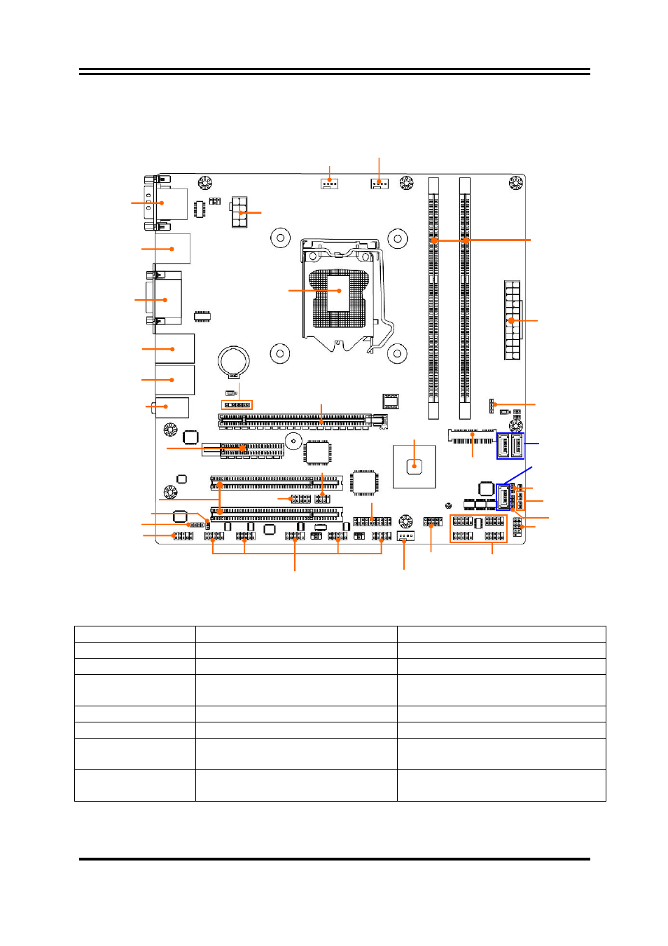
Motherboard Internal Diagram
--For NMF95-H81:
Note:
1. The main differences between the two models are listed as below:
Differences
NMF95-Q87
NMF95-H81
Chipset
Intel Q87 Chipset
Intel H81 Chipset
DIMM Slot
4*Slot (DIMM1/2/3/4)
2*Slot (DIMM1/3)
SATA Port
5*SATA 6Gb/s Port
(SATA1/2/3/4/5)
2* SATA 6Gb/s Port(SATA1/2)+
1* SATA 3Gb/s Port (SATA5)
USB 2.0 Header 2*Header (USB3/4)
1*Header(USB3)
USB 3.0 Header
1*Header (USB2)
N/A
PE2 Slot
PCI Express 2.0 x 4 slot,
Running by x4 bus
PCI Express 2.0 x 4 slot,
Running by x2 bus
MSATA Slot
Function optionally as MSATA
or Mini-PCIE slot
Function only as MSATA slot
2. The other diagrams used for illustration in this manual are from model NMF95-Q87,
unless otherwise stated.
ATX 12V
Power Connector
ATX Power
Connector
LGA 1150
CPU Socket
Audio Connectors
USB 3.0 Ports
over HDMI Port
VGA Port over
DVI–D Port
RJ-45 LAN Ports
Over USB 2.0 Ports
RJ-45 LAN Ports
Over USB 2.0 Ports
PCI Express x16 Slot (PE1)
PCI Express 2.0 x 4 Slot (PE2)
32-bit PCI Slots
Front Panel
Audio Header
CDIN Header
TPM Header
Intel H81
Chipset
USB 2.0 Header
(USB3)
Front Panel Header
DDRIII
DIMM Slot x 2
SYS FAN1 Header
GPIO Header
SYS FAN2 Header
KBMS Header
CPUFAN Header
SM_BUS Header
SATAIII Ports
(SATA1/2)
HDMI_SPDIF Header
PWR LED Header
Serial Port over
Display Port
NICLED Headers
*Full-size
MSATA Slot
(MSATA)
CIR Header
Serial Port Headers
(COM5/6/3/2/4)
Serial Port Headers
(COM7/8/9/10)
Speaker Header
SATAII Port
(SATA5)