2 cob ids, 3 status led – ifm electronic JN2100 v.2.2.0 User Manual
Page 31
UK
Inclination sensor JN
31
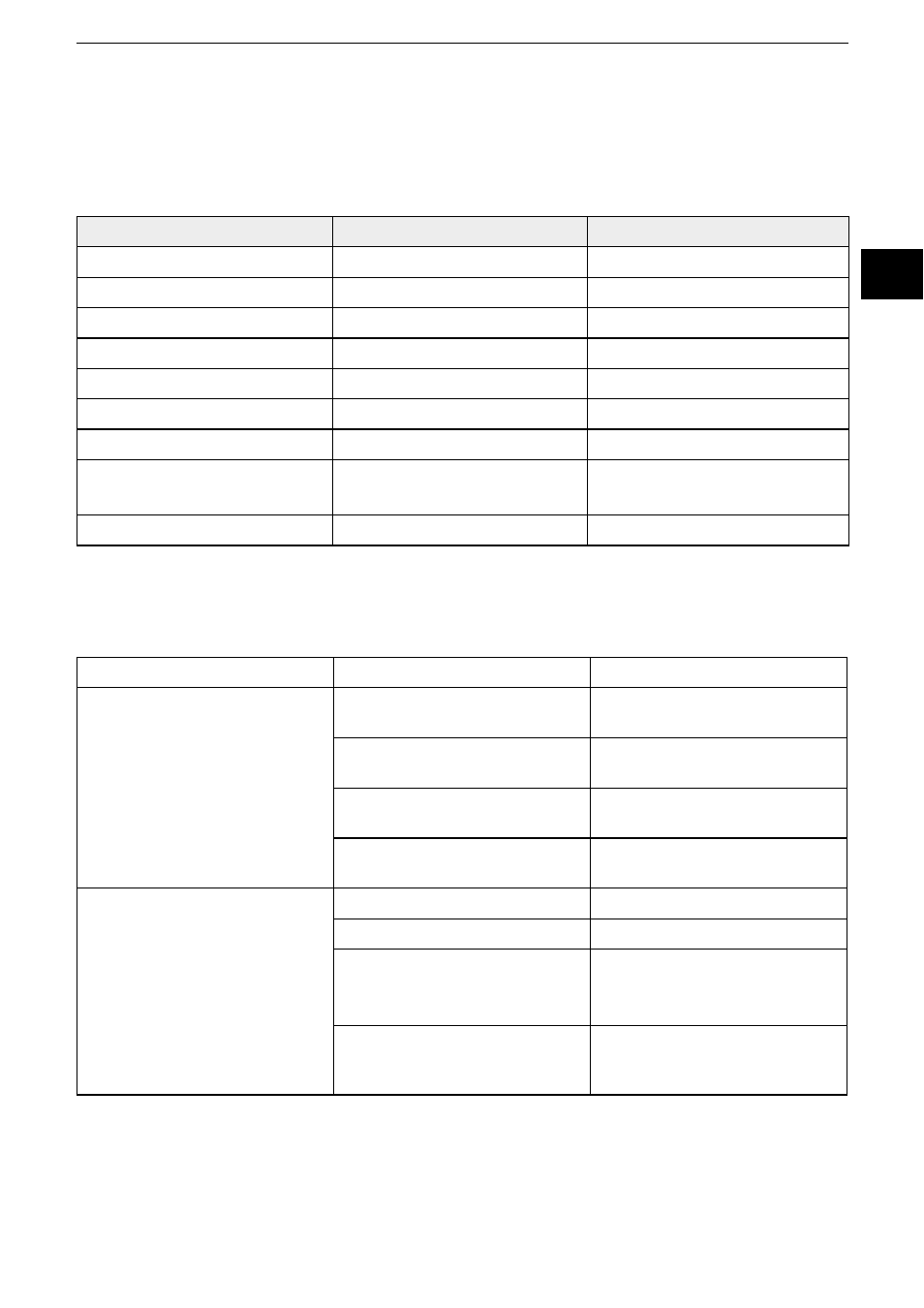
12.2 COB IDs
The CAN identifiers of the communication objects are determined according
to the pre-defined connection set with every reset (communication, application
and hardware reset) depending on the set node ID (SDO index 2000h).
Communication object
Calculation of the COB ID
Default value (node ID = 10)
NMT0 h
0h
SYNC
80h
80h
EMCY
80h + node ID
8Ah
TPDO0
180h + node ID
18Ah
TPDO1
280h + node ID
28Ah
TPDO2
380h + node ID
38Ah
TPDO3
480h + node ID
48Ah
Standard SDO
(client
→
server)
580h + node ID
58Ah
Heartbeat
700h + node ID
70Ah
12.3 Status LED
The integrated LEDs indicate the current device status (run LED, green) and CAN
communication errors (error LED, red).
LED colour
Flashing frequency
Description
Green
Permanently off
The device is in the "reset" state
or no power supply is available
Permanently on
The device is in the
"pre-operational" state
Flashes
The device is in the
"operational" state
Brief lighting once
The device is in the "stopped"
state
Red
Permanently off
No error
Permanently on
The device is in the "bus off" state
Brief lighting once
Error counter:
The CAN controller has reached
or exceeded its warning limit
Brief lighting twice
The device has detected the
failure of the guarding master
(node guard event)