Gullco GK-203-400-12 User Manual
Page 9
7
SETUP
Before powering up the E.A.H.S. make sure all components and cables are properly
connected. There are three (3) major components to the E.A.H.S. system; the sensor
control box, the remote pendant and the 4” linear slide. In order for the E.A.H.S. system to
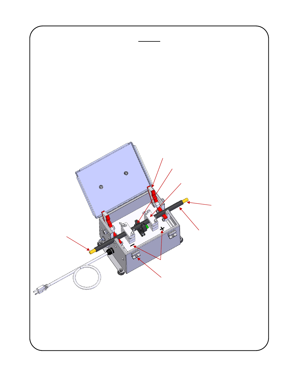
operate, the welding ground cable must be routed through the sensor control box. The
direction of current flow or polarity is important or the E.A.H.S. will not be able detect
current thus not allowing it to track the arc height automatically. To open the sensor control
box loosen the lid clamping screws until the lid can be opened. Inside the control box there
are two (2) cable dust covers, two (2) cable clamps and the current sensor. To install the
welding ground cable open both dust covers and remove the wing screws on both cable
clamps. Remove small Phillips screw from the current sensor and open it. Place the
welding ground cable inside, shown below. Then close the current sensor reinstalling the
Phillips screw and tightening the cable clamps. Close the dust covers and the lid, then
tighten the lid clamp screws.
For electrode negative setup (“-“ torch), flip the orientation of the welding ground in relation
the control box, the “+” reference will face welding power source while the “-“ reference will
face the work piece.
Note: Care should be taken to ensure that no foreign debris enters the main control box,
periodically check the condition of the foam gaskets and replace any that are damaged or
defective.
Dust cover
Cable clamp
Current sensor
Welding ground
cable
Electrode positive setup
(“+” torch)
Return path back to
welding power
source “-“ terminal
Work piece ground
connection
Polarity reference
marks
Lid clamp
screw