Gullco GK-203-400-12 User Manual
Page 14
12
DS72 Switch 1 and 2 is used to calibrate the control to the type of slide. The standard slide (GK-
203-001) is factory set. The optional Heavy Duty slide (GK-203-007) is only available on the GK-
203-800 (800 amp). See below table. Note: when changing slides, Dip switch S42 on the motor
control board has to be set as well.
DS72 Switch 3 is used to set the top and bottom orientation of the slide. Depending on how the
linear slide is mounted relative to the control, the top & bottom locations and manual jog (steering)
may be opposite to that expected. This field allows virtual orientation reversal of the linear slide.
The choices available are either “top/bottom” or “bottom/top”. The control will also reassign limit
switch input logic to suit. See below table.
DS72 Switch 4
is non-functional and for future use.
DS73 Switch 1 to 4
are non-functional and for future use.
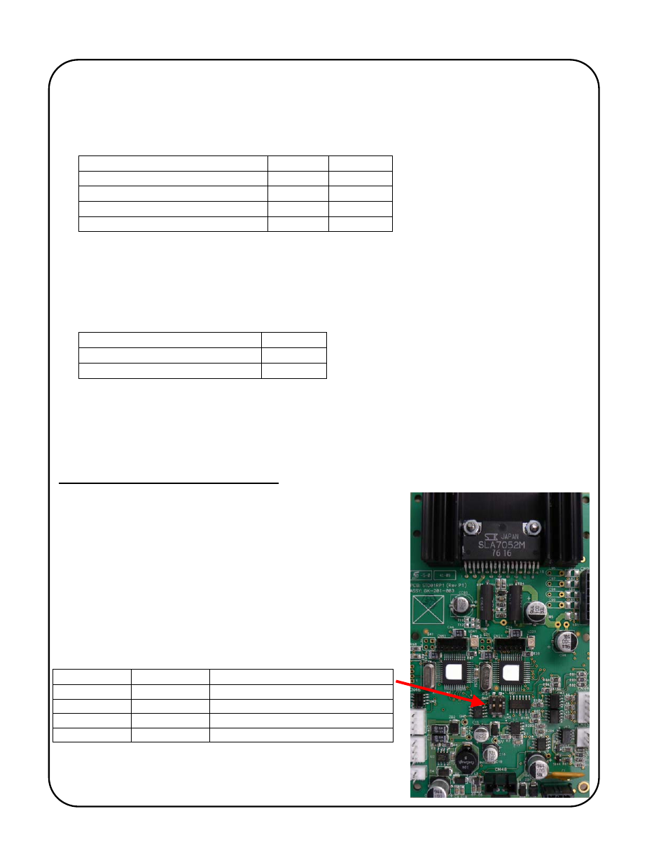
Motor Board Dip Switch (S42) Settings
Dip Switch S42, is located on the back of the motor control
board inside the remote pendant. This switch is used to
calibrate the motor board to the type of slide. The standard
slide (GK-203-001) is factory set. The optional Heavy Duty
slide (GK-203-007) is only available on the GK-203-800 (800
amp). See below table. Note: when changing slides, Dip switch
DS72 on the back of keypad control board (inside the remote
pendant control) has to be set as well.
Linear Slide Type
SWITCH 1 SWITCH 2
STD SLIDE GK‐203‐001 (factory set)
up
up
HD 4" SLIDE GK‐203‐007
down
up
N/A
up
down
N/A
down
down
"top" and "bottom" Orientation
SWITCH 3
"top/bottom" (factory set)
up
"bottom/top"
down
SWITCH 1
SWITCH 2
SETTINGS
Off
Off
Heavy Duty slide (GK-203-007)
On
Off
Standard slide (GK-203-001)
Off On Future
use
On On Future
use