Maintenance – Groth 1200A User Manual
Page 6
5
MAINTENANCE:
Groth Corporation recommends that all service
performed on a pressure/vacuum relief valve be
done at the factory or a factory authorized repair
center. Trained mechanics with specialized test
equipment will ensure that the valve is accurately
set.
It is important to regularly inspect the diaphragm,
guides (body & cover) and seating surfaces to
ensure the valve can open freely. Refer to Fig. 5 -
7 on the next page which illustrate a typical
Pressure/Vacuum relief valve when disassembling
the unit. Also inspect the valve body – especially
at all tie-ins between flange & pipe sections for
signs of corrosion or deterioration.
WARNING: Before disassembling valve carefully
read and understand the Safety Warnings listed on
page 3.
1. Loosen and remove all nuts and washers.
2. Lift off the pressure and/or vacuum cover(s).
The weatherhood and weatherhood posts have a
snug fit. Loosen the hex nuts that retain the
weatherhood posts in the body a few turns; this will
allow the weatherhood to be removed easily.
3. Remove the pressure and/or pallet assembly(s)
by firmly grasping the stem and lifting straight up.
Depending on the pressure/vacuum settings of the
particular valve, weight plates are added to the
pallet assembly. (Note that in most instances,
these are integral with the pallet.) The weights and
pallets MUST be reinstalled in their original
locations. Make sure that all weight plates stay
with the appropriate pallet assembly. Tag the
assemblies "Pressure" and "Vacuum" as they are
removed from the valve.
4. Carefully inspect the body for corrosion,
damage or product build up. Also inspect the guide
hole in the vacuum cover. Check the seating
surfaces for pitting, corrosion or product build up.
It is recommended that all soft goods including
diaphragms, O-Rings and cover gasket are
replaced. For a list of recommended spare parts
see the drawings on pages 8 – 13.
NOTE: If the seat(s) are damaged, it is
recommended that the body be returned to the
factory for repairs.
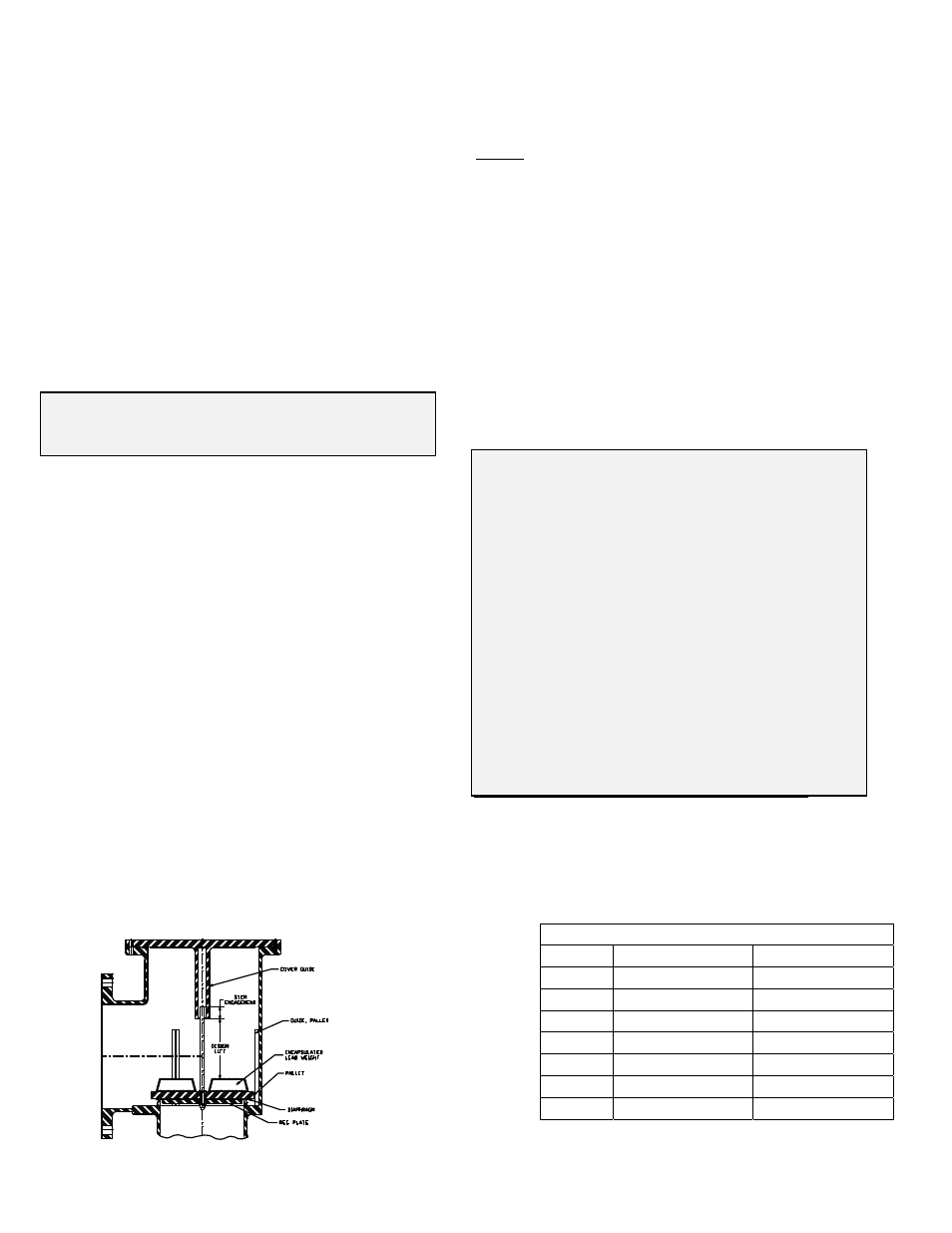
5. If the stems are replaced, verify that the
replacement component is the same length as the
original stem. Note that stem engagement in the
guide is approximately 0.75” for 2” - 4” sizes and
1.00” for 6” - 12” sizes.
6. Verify that the pallet assembly(s) are installed
in the proper location. Assemble in reverse order.
Make sure that pallet is flat on the seat and that
the stem is not cocked at an angle when the
weatherhood and pressure/vacuum cover(s) are
installed. Tighten all fasteners firmly.
WARNING: When assembling a P/V valve,
always use the correct length stem, put the
pressure and vacuum pallet assembly(s) back in
their original location and ensure that the stem is
straight and fits into the guide in the cover or
weatherhood.
1. If the stem length is too long, pallet lift will be
restricted; the valve will not attain its full rated
flow capacity.
2. If the pressure and vacuum pallet assemblies
are mixed at assembly, the settings will be
changed.
3. If the stem is cocked at an angle, pallet lift may
be completely blocked.
An over-pressure can occur if any of these three
conditions happens. This can cause a tank failure,
severe personal injury and material damage.
Fig. 4
Required
Pallet
Clearance
Required Pallet Clearance
Size Pressure
Vacuum
2” 1.3”
1”
3” 1.95”
1.5”
4” 2.6”
2”
6” 3.9”
3”
8” 5.2”
4”
10” 6.5”
5”
12” 7.8”
6”