Groth 1200A User Manual
Page 2
© Copyright Groth Corporation 1999
1
TABLE OF CONTENTS:
DESCRIPTION
PAGE
Introduction 1
Valve Design & Function
2
Safety Warnings
3
Inspection and Storage
3
Installation
3 - 4
Maintenance
5 - 6
Test Procedure
7
LIST OF FIGURES
Fig. 1- Typical Tank Installation
2
Fig. 2- Pressure Relief - Operation
2
Fig. 3- Vacuum Relief - Operation
2
Fig. 4- Required Pallet Clearance
5
Fig. 5- Pallet Assembly Detail - FRP
6
Fig. 6- Pallet Assembly Detail - Kynar
6
Fig. 7- Typical Valve Cross-Section
6
Fig. 8- Model 1200A Valve
8
Fig. 9- Model 1220A Valve
9
Fig. 10- Model 1260A Valve
10
Fig. 11- Model 1300A Valve
11
Fig. 12- Model 1360A Valve
12
Fig. 13- Model 2300A Valve
13
Model Identification
15
Product Limited Warranty
15
LIST OF TABLES
Table 1 - Bolt Torque (Installation)
4
Table 2 - Fiberglass Valve Weights
4
Table 3 - Spare Parts P/N
5
Table 4 - Pallet Assembly Weights
6
Table 5 – List of Abbreviations
14
Table 6 – FRP Resin Options
14
INTRODUCTION:
Pressure and/or vacuum relief valves are used on
liquid storage tanks and other process vessels or
systems to prevent structural damage due to
excess internal pressure or vacuum.
Storage tanks are pressurized when liquid is
pumped in, compressing the existing vapor or
when rising temperatures cause increased
evaporation or expansion of existing vapor.
Conversely, a vacuum condition may be created
when pumping out or due to falling temperature.
To prevent tank damage, vapor must be allowed
into or out of the tank at specified
pressure/vacuum conditions. The volume rate of
venting depends upon the tank size, volatility of
the tank contents, the pumping rates and the
temperature. Refer to API Standard 2000 for the
procedures to determine venting requirements.
Relief valves must be carefully maintained by a
qualified valve technician. It should only be
assembled under clean conditions, preferably in a
service shop environment. Carefully read and
understand this manual before installing or
attempting to repair a valve. Groth Corporation or
a factory authorized repair center offers repair
services for all products manufactured by the Tank
Protection Division.
The table below shows the six different valve
Models covered in this manual and indicates their
Pressure (P) and/or Vacuum (V) relief capabilities.
Model
P V
Description
1200A
Vent to atmosphere
1220A
Vent to Header
1260A/
1760A
Vent to Header
1300A
Top mounted
1360A
Side mounted
2300A
Vent to atmosphere
For a list of abbreviations used in this manual,
refer to page 14. For information not contained in
this manual, please contact:
Groth Corporation
13650 N. Promenade Blvd
Stafford, Texas, 77477
281-295-6800(Phone)
281-295-6995(Fax)
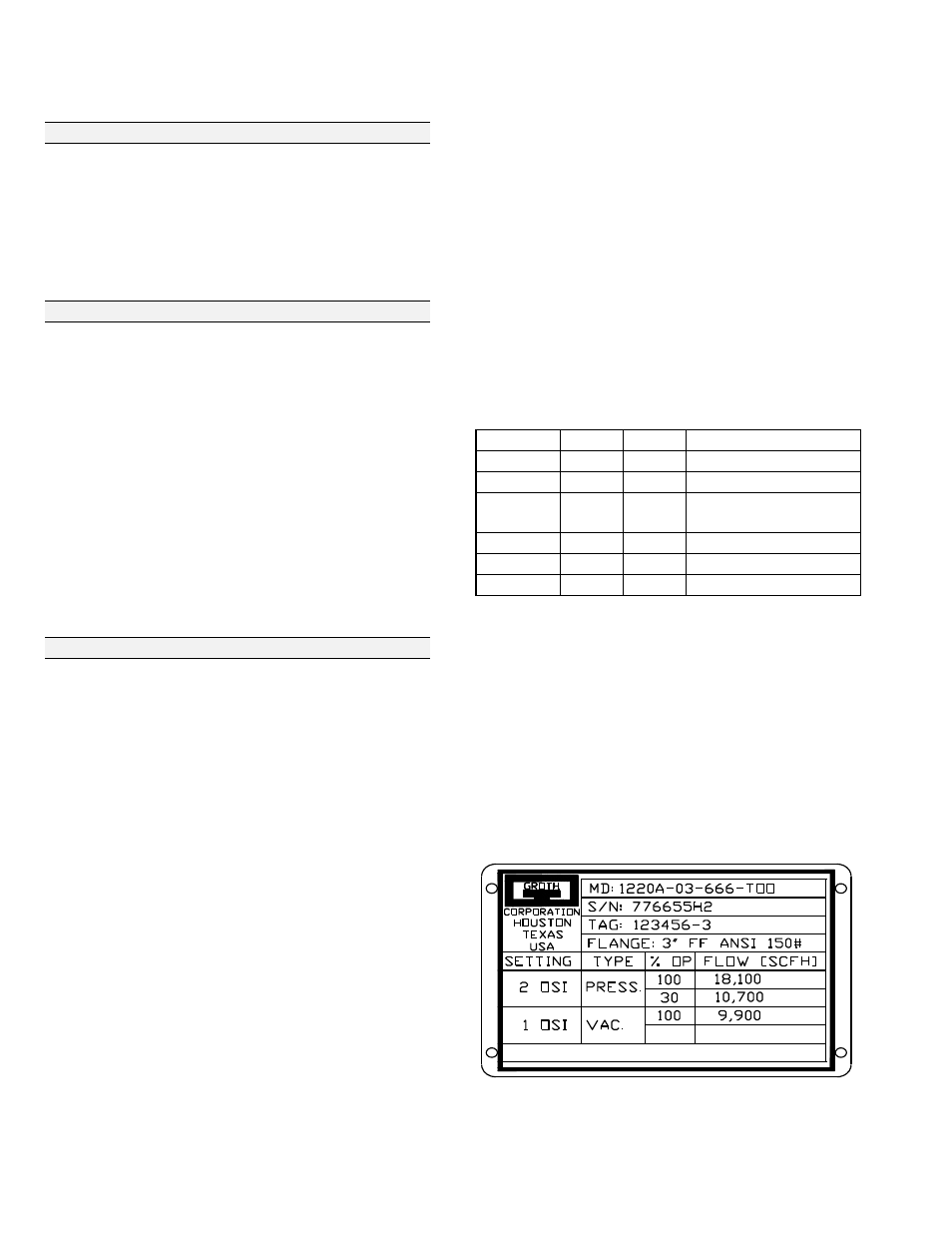
The nameplate below shows the basic information
that is listed for each relief valve: