Groth 1200A User Manual
Page 5
4
The following guidelines should be
observed at installation:
1. Inspect the gasket seating surface of the tank
nozzle flange. It must be clean, free of
scratches, corrosion, tool marks, and flat.
2. Fiberglass valves are furnished with flat face
flanges; they must ONLY be installed on a
mating flat face flange with a full faced gasket.
3. Inspect the gasket; make sure that the material
is suitable for the application.
4. Lubricate all studs and nuts with an
appropriate thread lubricant. If the valve will
see high temperature service or stainless steel
fasteners are used, apply an anti-seize
compound such as moly-disulfide.
5. Center the gasket within the bolt circle.
6. Lift the valve carefully using one or more
fabric slings to support both pressure &
vacuum chambers.
7. Set the valve carefully on the nozzle. Install
the studs & tighten nuts hand tight.
8. Torque all fasteners to half the value listed
in Table 1 in a staggered, alternating
pattern.
9. Make sure that the flanges are not
distorted and that the gasket is evenly
compressed. Make up the final torque and
check that no further nut rotation occurs at
the torque value specified in Table 1
below:
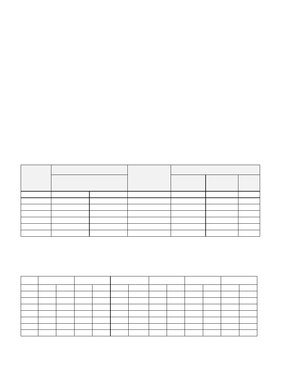
TABLE 1 - Bolt Torque & Stud Specifications - ANSI #150 FF Flange Connections
Mounting
Bolt Torque
Number Bolts
Stud Specifications
Flange
Flat Face
Lb. - Ft. kg. - m
Total
Thread
UNC
Stud
Length
Qty
2"
25
3.5
4
5/8" - 11
3.00
4
3"
40
5.5
4
5/8" - 11
3.50
4
4"
40
5.5
8
5/8" - 11
3.50
8
6"
40
5.5
8
3/4" - 10
3.75
8
8"
55
7.5
8
3/4" - 10
4.00
8
10"
60
8.5
12
7/8" - 9
4.50
12
12"
80
11.0
12
7/8" - 9
4.50
12
Notes:
1. Do
NOT bolt a FF FRP body to a RF tank nozzle.
2. Stud Length is based on standard ANSI mating flange, standard hex nut and two narrow series flat washers.
TABLE 2 – Fiberglass Valve Weights
Size 1200A
1220A 1260A/1760A 1300A
1360A
2300A
Lb. Kg. Lb. Kg. Lb. Kg. Lb. Kg. Lb. Kg. Lb. Kg.
2"
18 8.3 20 9.3 13 5.9 5 2.3 8 3.8 10 4.4
3"
32 14.6 36 16.4 23 10.4 10 4.4 11 4.8 18 8.0
4"
49 22.5 55 24.9 36 16.5 15 7.0 16 7.3 26 11.9
6"
101 45.7 114 51.8 73 33.3 29 13.1 31 14.1 51 23.2
8"
149 67.8 168 76.6 112 50.7 46 20.7 44 20.1 78 35.5
10"
219 99.4 233 105.9 159 72.2 66 29.9 60 27.5 123 55.7
12"
289 131.6 314 142.7 216 98.1 95 43.2 77 34.9 167 76.0
Note: Based on pressure setting = 1 PSIG & Vacuum setting = 2 Oz./Sq.In. (where applicable)