User interface, Wiring, Optional remote override – Greenheck Vari-Green Control - Indoor Air Quality - Temp/Humidity (475573) User Manual
Page 4: Optional output reference, Display features, Normal operation (j19 = run)
4
User Interface
A scroll button protrudes through the case. The
programming switches and programming jumper are
inside the case.
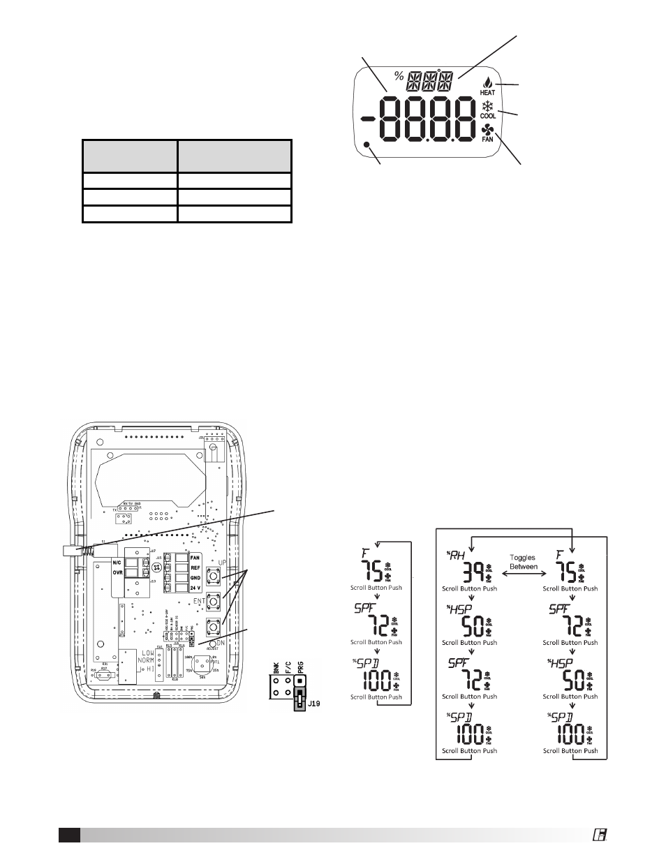
Minor Display
0.34 inch 3-digit
Alpha-Numeric
Main Display 0.76
inch 4-digit Numeric
Dot
Controller
Terminal
Transformer
Control Terminal
J15-FAN
0 to 10V
J15-GND
COM
J15-24V
24V
Wiring
All wiring for the Greenheck Temperature and
Humidity Controller is Class II low-voltage control
wiring. See the Wiring Diagram on Page 7 for the
wiring overview.
Optional Remote Override
Connect a normally-open switch between terminals
J17-OVR and J15-GND on the controller. Closing
this switch will activate the remote override feature.
Opening the switch will de-activate the override.
Optional Output Reference
A 0 to 10VDC signal is available from J15-REF to
J15-GND. The signal is 15° to 130° F (-10° to 55°C)
or 0 to 100% Relative Humidity depending on the
value of parameter P10 (see pg 6).
Control box to factory mounted
transformer control input.
Scroll
Button
Programming
Jumper in
RUN Mode
Fan ON Icon
Programming
Switches
Heat Control
Icon
Cool Control
Icon
Display Features
The minor display is used to describe the units
displayed and the main display shows the numeric
value. The fan icon is illuminated whenever the fan
output voltage is at or above the minimum specified
in parameter P8, Minimum % Fan Speed. The Cool
and Heat Icons are illuminated in each control mode
respectively. The dot in the lower left is used to
signal fan cut-out mode.
Normal Operation (J19 = RUN)
The Greenheck Indoor Air Quality – Temperature/
Humidity Controller ships with the following factory
setting: Cooling Control, Temperature Setpoint 72°F,
Fan Control output at 2 to 10 Volts and Cut-Out
Disabled. Pressing the scroll button at any time
shows the Temperature setpoint, a second push
shows the fan speed in percent.
The scroll button will change the display momentarily
to view other information such as setpoints and fan
speed. These are for reference only, and cannot
be adjusted. The exact sequence will depend on
the settings of parameters P0, P1, P2 and P4. For
examples, see the two figures below.
Scroll Button Sequence,
Temperature & Humidity Control
Cooling Mode, °F Temperature
and Display in run.
Scroll Button
Sequence,
Temperature
Control
Cooling Mode,
°F Temperature
and Display in
run.