Constant pressure control, Wiring – Greenheck Vari-Green Control - Constant Pressure Indoor (474766) User Manual
Page 4
4
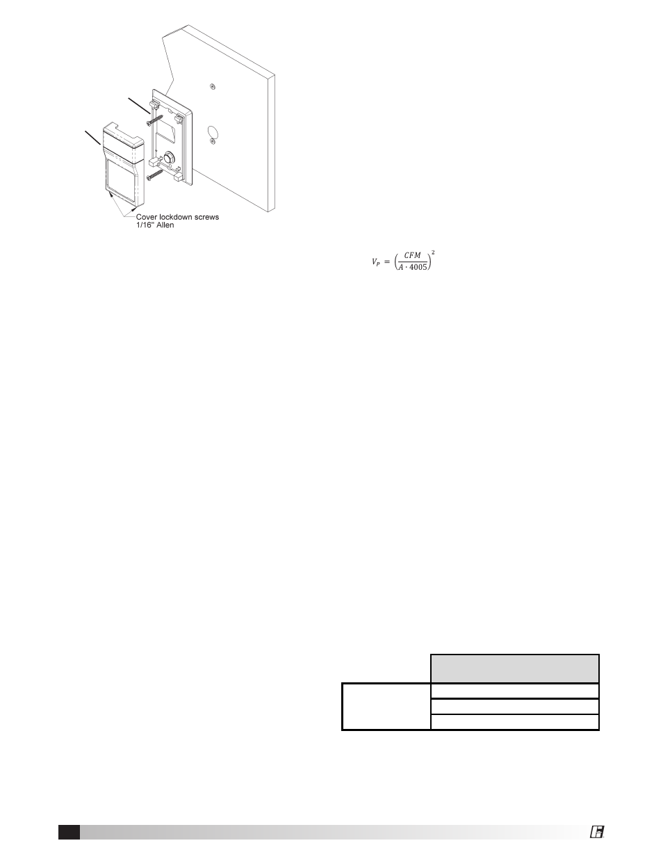
Wall Mount
1. Using a 1/16” Allen wrench, separate the mount-
ing base and the cover by driving in the 1/16” Allen
screws until the cover comes free. Driving the
screws in prevents you from losing them.
2. Drill a ¾” hole in the drywall to relieve the pressure
fitting where the pressure tap is to be installed.
3. Place the mounting base pressure fitting in the ¾”
hole and align the mounting base to the wall.
4. Using a pencil, mark out the two mounting holes on
the wall.
5. Drill two 3/16” holes in the center of each marked
mounting hole. Insert a drywall anchor into each hole.
6. Pull the pressure tubing through the wall and out of
the 3/4” hole, leaving about two inches free.
7. Secure the pressure tubing to the pressure fitting.
8. Secure the base to the drywall anchors using the
#6 x 1 inch mounting screws provided.
9. Attach Cover by latching it to the top of the base,
rotating the cover down and snapping it into place.
10. Secure the cover by backing out the lock-down
screws using a 1/16” Allen wrench until they are
flush with the bottom of the cover.
Constant Pressure Control
• The Constant Pressure Control contains an
integral pressure transducer.
• Mount the Constant Pressure Control box in
an accessible location as close as possible to
the pressure tap and fan. Keep wiring lengths
between the Constant Pressure Control and the
fan to 200 feet or less. Keep pressure tubing
lengths between the Constant Pressure Control
and the pressure taps to 100 feet or less.
• Mount the Constant Pressure Control in the
vertical position with the tubing connectors in the
down position.
•
One Duct Tap – Maintains constant pressure
in duct based upon space pressure where the
Constant Pressure Control is mounted – Connect
the “H” tubing connector on the Constant
Pressure Control to the pressure tap using 1/4-
inch tubing. The “L” tubing connector remains
open to atmosphere.
•
One Duct Static Tap and One Duct Total Tap –
Maintains a constant velocity pressure in a duct.
This allows the system to automatically adjust the
airflow in a system to compensate for filter or coil
loading. Connect the “H” tubing connector on the
Constant Pressure Control to the total pressure
tap and connect the “L” tubing connector to
the static pressure tap using 1/4” tubing. The
resultant measurement will be velocity pressure.
•
System Balancing – The Constant Pressure
Controller can maintain a velocity pressure from
0 to 1”. To balance the system, calculate the
velocity pressure required for the system based
on the intended CFM and duct area:
Where A is the duct area in ft
2
.
Set parameter P11=0 and parameter P01 (the
pressure setpoint) to the desired velocity
pressure. If airflow verification is needed, external
CFM measurements can be taken and the
velocity pressure can be adjusted until the
desired airflow is achieved.
•
One Room Tap – Maintains constant pressure in a
room based upon space pressure where the Con-
stant Pressure Control is mounted – Connect the “H”
tubing connector on the Constant Pressure Control
to the pressure tap using 1/4-inch tubing. The “L”
tubing connector remains open to atmosphere.
•
Two Room Taps – Maintains a constant
differential pressure between two rooms, allowing
the Constant Pressure Control to be mounted in a
remote location - Connect the “H” tubing connector
on the Constant Pressure Control to the pressure
tap in the high pressure room using 1/4-inch
tubing. Connect the “L” tubing connector on the
Constant Pressure Control to the pressure tap in
the low pressure room using 1/4-inch tubing.
• Make sure the tubing is not kinked or punctured.
Wiring
See diagram on page 7 for wiring overview.
• Control Box to Factory Mounted Transformer
Control Input
• Optional Remote Override:
Connect a normally-open switch between terminals
J3+ and J3- on the controller. Closing this switch will
activate the remote override feature. Opening the
switch will de-activate the override.
Controller
Terminal
Transformer
Control Input
J1 - POWER
to 24V
J1 - GROUND
to COM
J1 - OUTPUT
to 0-10V
Low-voltage
control wiring
Wall Mount
Mounting Plate
Cover