Effects of installation on performance, Controlling vibration, Vibration isolators – Greenheck Vane Axial Fans (452954) User Manual
Page 4: Flexible duct connectors
Effects of Installation on
Performance
System Effect - Inlet and outlet conditions greatly
affect the air performance of a vane axial fan. The Air
Movement and Control Association (AMCA) defines
system effect as “a pressure loss which recognizes the
effect of fan inlet restrictions, fan outlet restrictions,
or other conditions influencing fan performance when
installed in the system”.
System effect is very difficult to quantify and correct.
Frequently, the only means to correct the resulting poor
performance is to increase fan speed or blade pitch in
the hope of overcoming the additional pressure loss.
This may result in overloading the motor and require
motor replacement. In extreme cases, the entire fan may
need to be replaced if the system effect is severe.
The following diagrams show common inlet and outlet
conditions. Minimum recommended distances are
shown to minimize system effect on the ducted and
non-ducted installations.
Non-Ducted Inlets - Greenheck recommends inlet bells
on all non-ducted inlets. An inlet bell smooths airflow
into the impeller blade tips providing uniform impeller
blade loading. An inlet without an inlet bell creates non-
uniform airflow resulting in poor performance, vibration
and noise.
Inlets in Proximity to Walls - Vane axial installations
with a non-ducted inlet too close to a wall or other
obstruction may create reduced fan performance.
Greenheck recommends a minimum of one fan diameter
between a wall and the fan inlet.
Ducted Inlets - Inlet ducts must provide smooth non
turbulent airflow into the impeller blades. Any elbows,
transitions, dampers or other disruptions close to
the fan inlet will create system effect and reduce fan
performance.
Non-Ducted Outlets - Greenheck recommends an
outlet cone be attached to all non-ducted outlets. An
outlet cone reduces velocity pressure losses resulting in
lower brake horsepower and higher efficiency.
Outlets in Proximity to Walls - Vane axial outlets
should be no closer than two fan diameters from any
wall. Fans with less than this distance will experience
significant performance losses.
Ducted Outlets - Ducted outlets require a straight,
uniform diameter length of ductwork immediately
after the fan outlet. Sharp turns or elbows close to
the outlet will create system effect losses and poor air
performance. Greenheck recommends a minimum of
three fan diameters between the fan outlet and any duct
turn.
Controlling Vibration
Vibration Isolators
Although vane axial fans are typically very smooth
running fans, any residual vibration will be transmitted
and amplified through flooring, ceilings and ductwork.
To prevent a small amount of vibration from becoming
a large amount of noise, vibration isolators are
recommended for floor mount or ceiling hung
installations.
The most common isolators are:
Isolator Type
Application
Free-Standing Spring
Permits radial and axial vibration
dampening.
Housed Spring
Permits radial and axial vibration
dampening where less motion can
be tolerated.
Restrained Spring
Used where large weight changes
or high wind loads occur. Upward
vertical movement is prevented by
mechanical restraints.
Seismic Control
Restricts movement of supported
equipment during earthquakes
while providing isolation.
Spring Hanging
Provides vibration isolation of
suspended equipment. Threaded
suspension rods typically are
supplied by the installer.
Rubber-in-Shear
Neoprene isolators are highly
effective for relatively small fans
with speed of 1800 RPM and over.
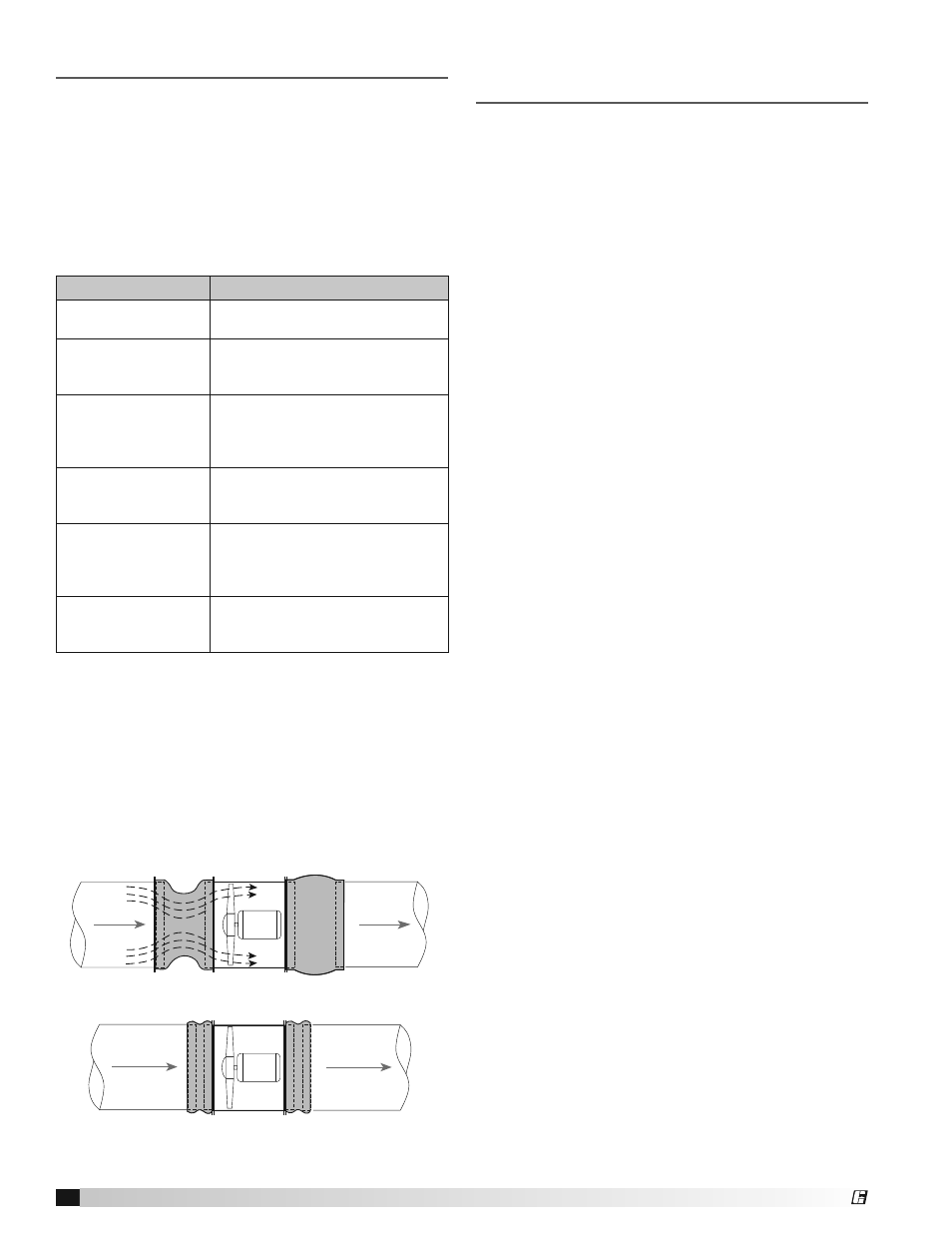
Flexible Duct Connectors
Flexible duct connectors should be taut between the fan
inlet and the connecting duct. Loose flexible connectors
will cause “necking” of the airstream when installed
on the negative pressure side of the fan. This will
create non-uniform airflow into the fan inlet and starve
the impeller blade tips of air. Therefore, the flexible
connector should not be loose and should be just long
enough for mechanical isolation. See Fig. 3 for flexible
connectors.
Poor
Good
Fig. 3 Flexible Duct Connectors
4
Vane Axial Fans
®