Gas piping instructions, Warnings, Piping guidelines – Greenheck TSU Direct Gas Manual (456857) User Manual
Page 3: Location of gas connection, Leak testing components, High pressure testing
3
Piping Guidelines
All gas piping must be installed in accordance with the National Fuel Gas Code ANSI/Z223.1 - latest edition and any
local codes that may apply. In Canada, the equipment shall be installed in accordance with the Installation Code for
Gas Burning Appliances and Equipment, CGA B149, and Provincial Regulations for the class; which should be
carefully followed in all cases. Authorities having jurisdiction should be consulted before installations are made.
The nameplate on the direct gas section door describes all the requirements about the gas being supplied to
the unit. For typical operation size 10 through size 30 units need a minimum of 6 in. to a maximum of 14 in. wg
for natural gas and 2 to 6 in. wg pressure for LP gas. Sizes 40 and 50 need a min. of 1/2 PSI to a max. of 5 PSI.
When the supply pressure exceeds the maximum pressure an additional regulator (furnished by others) is
needed to step down the pressure. The regulators in the unit are used to adjust the maximum output
temperature of the unit. Piping should be of adequate size to provide a sufficient supply of gas to meet the
maximum demand with minimal pressure loss between the meter and the unit.
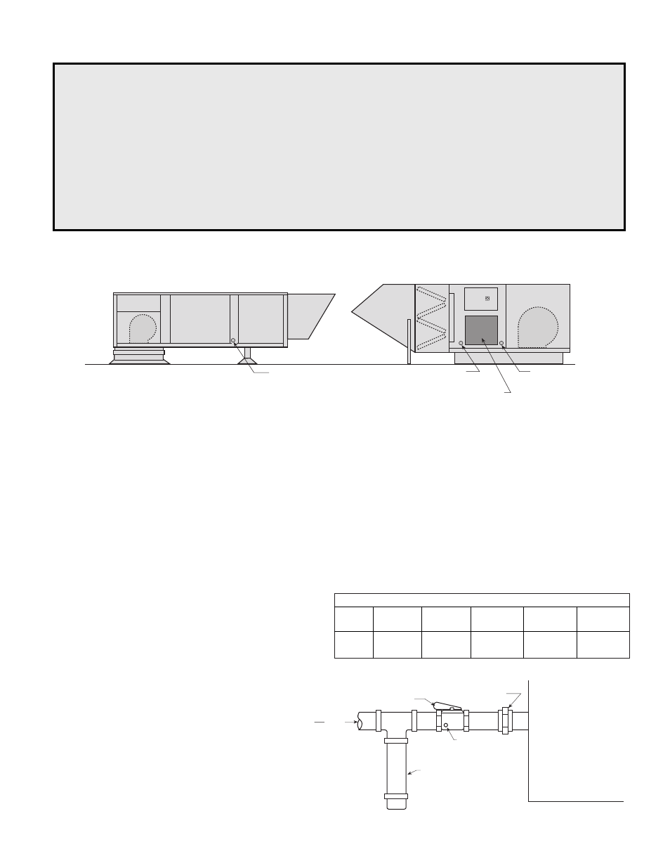
A manual shut off valve (gas cock) and a 1/8 in.
plugged tapping and a 6 in. drip leg must be installed
prior to the gas train and must be accessible for
connection to test gauge.Connections are to be made
by a qualified installer and are not furnished by
Greenheck.
Finally, check for leaks in the supply lines to
the unit. The factory piping has been checked
for leaks, but should be rechecked due to
shipping and installation. See leak test
warnings above.
All piping should be clean and free of any
foreign matter. Foreign material entering the
gas train can cause problems with the valves,
regulators, and the burner.
Gas Piping Instructions
Location of Gas Connection
Warnings
Leak Testing Components
All components of this or any other gas fired heating unit must be leak tested prior to placing the unit into
operation. A soap and water solution should be used to perform this test. NEVER test for gas leaks with an
open flame. See page 10 for safety shut off valve leak testing.
High Pressure Testing
The heater and its individual shutoff valve must be disconnected from the gas supply piping system during
any pressure testing of that system at test pressures in excess of 1/2 psig (3.5 KPa).
The heater must be isolated from the gas supply system by closing its individual manual shutoff valve during
any pressure testing of the gas supply piping system at test pressures equal to or less than 1/2 psig (3.5 KPa).
From
Gas
Gas Cock
1/8 in. Plugged Tap
6 in. Trap
Ground Joint Union
Make-Up Air Unit
Standard Inlet Gas Pipe Size
Max.
400,000
1,375,000 2,475,000
4,400,000
<400,000
BTUs
1,375,000 2,475,000 4,400,000
5,500,000
Pipe
3
/
4
in.
1
in.
1
1
/
2
in.
2 in.
2
1
/
2
in.
Size
Gas Line Connection
Housing 40
Direct Gas
Train Door
Gas Line Connection
Housing 50
Housing Size 40 & 50
Housing Size 10-30
Gas Line
Connection