Sequence of operation, Control sequence, Control sequence - variable air volume (optional) – Greenheck Packaged DX Module (474681) User Manual
Page 7
7
Packaged DX Module for Make-Up Air Unit
Sequence of Operation
The compressors are energized by an outdoor air
thermostat TS5, located in the unit control center. The
thermostat sensor is located in the intake airstream
upstream of the DX coil. The thermostat can be a single
or dual stage thermostat depending on the number of
compressors. The first stage of cooling will energize
when the outdoor air temperature rises above the
thermostat set point plus the differential. The thermostat
is factory set at 80°F with a differential of 5°F but can
be field adjusted. The second stage of cooling will
energize when the outdoor air temperature rises above
the second stage offset plus the differential. The second
stage offset is factory set at 10°F and the second
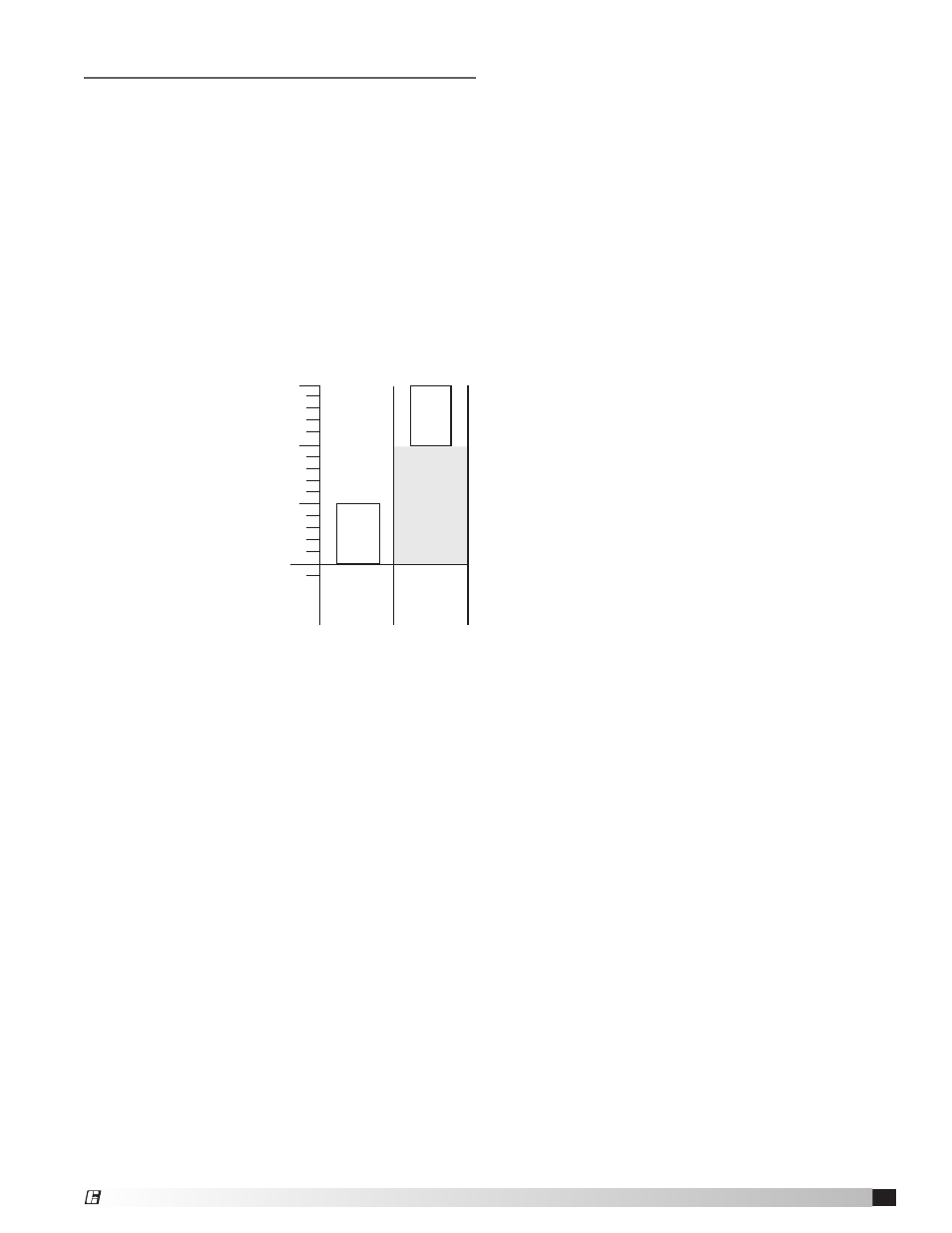
stage differential is set at 5°F. See the chart below for a
graphical representation of the control operation.
To summarize the
cooling controls,
the first stage of
cooling will turn
on at 85°F and the
second stage of
cooling will turn
on at 95°F. The
second stage of
cooling will turn
off at 90°F and
the first stage of
cooling will turn
off at 80°F.
Control Sequence
1. Fan switch needs to be closed (S3) between
terminals R and G.
2. Heating/Cooling switch (S4) is closed between
terminal R and Y1.
3. N.O. contact on fan relay (RF) is energized and
closed.
4. When the outdoor air temperature is above the set
point plus the differential power passes through
N.O. contacts on outdoor air thermostat (TS5) and
energizes the cooling relay (RC1).
5. When the pressure switches LPS (refrigerant
low pressure switch) and HPS (refrigerant high
pressure switch) are in their normal state relay R10
will energize. Starting the first stage compressor
contactor.
6. When the outdoor air temperature is above the
second stage offset plus the differential power
passes through N.O. contacts on outdoor air
thermostat (TS5) and energizes the cooling relay
(RC2).
7. When the pressure switches LPS and HPS
(refrigerant high pressure switch) are in their normal
state relay R11 will energize, starting the second
stage compressor contactor.
Setpoint
Temperature
(factory set at 80° F)
Adjustable
Dif
fer
ential
Adjustable
Dif
fer
ential
OFF
OFF
ON
OFFSET
(factory set
at 10° F)
(+5° F)
(+10° F)
FIRST
STAGE
COOLING
SECOND
STAGE
COOLING
ON
Control Sequence - Variable Air Volume
(optional)
1. Fan switch needs to be closed (S3) between
terminals R and G.
2. Heating/Cooling switch (S4) is closed between
terminal R and Y1.
3. N.O. contact on fan relay (RF) is energized and
closed.
4. When the outdoor air temperature is above the set
point plus the differential power passes through
N.O. contacts on outdoor air thermostat (TS5) and
energizes the cooling relay (RC1).
5. When the pressure switches LPS (refrigerant
low pressure switch) and HPS (refrigerant high
pressure switch) are in their normal state relay R10
will energize. Starting the first stage compressor
contactor.
6. When the outdoor air temperature is above the
second stage offset plus the differential power
passes through N.O. contacts on outdoor air
thermostat (TS5) and energizes the cooling relay
(RC2).
7. When the pressure switches LPS and HPS
(refrigerant high pressure switch) are in their normal
state relay R11 will energize, starting the second
stage compressor contactor.
8. When the discharge air temperature drops below
the low temperature set point (TS9) factory set
at 55°F, the second stage compressor contactor
will de-energize, turning off the second stage
compressor.
9. The second stage compressor will re-energize when
the discharge air temperature rises above 75°F.
®