Component operation – Greenheck Packaged DX Module (474681) User Manual
Page 5
5
Packaged DX Module for Make-Up Air Unit
Component Operation
Compressor Components
Each Packaged DX module has a complete set of
compressor contactors, condenser fan contactors,
relays and certain integral safety controls located in the
module.
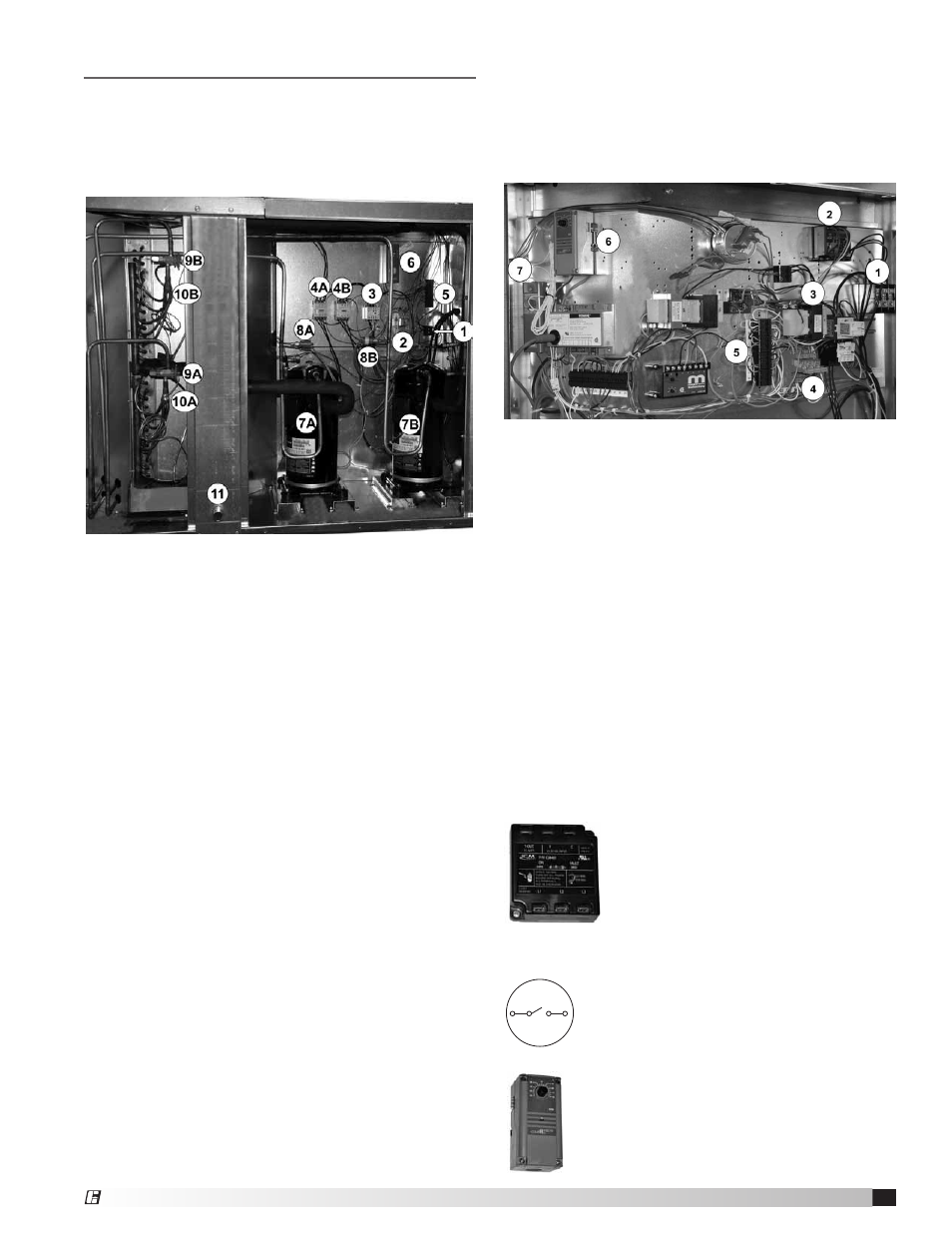
1. Power Distribution Block - field-supplied power
from main disconnect switch is terminated here.
2. Phase Monitor has jumpers going to power
distribution block)
3. Transformer provides 24 VAC to various low voltage
devices including the Phase Monitor and to Low
Voltage Terminal Strip in compressor compartment.
4. Relays RC1 and RC2 are wired to the control
center in the compressor compartment.
5. Low Voltage Terminal Strip - Switch S4 terminates
here.
6. Thermostat TS5 monitors outdoor air temperature
and turns the DX unit on or off.
7. Inlet Air Sensor monitors the incoming air
temperature and will disable the DX unit if ambient
temperatures are too low.
Additional Control Components
In addition to the control components located in the
PDX module, various high- and low-voltage circuits are
found in the Make-Up Air Unit control center. See the
unit-specific wiring diagram (found in the unit control
center) for complete information.
Phase Monitor constantly checks for
loss of a phase, phase unbalance or
phase reversal. It requires 24 VAC to
operate. When a fault is detected, it cuts
off the power supply to the low voltage
terminal strip, disabling all motors. It has
two LED indicator lights, showing “on”
and “fault”.
Switch S4 (not shown) is terminated on
Low Voltage Terminal Strip 5 above. S4
is field-supplied and field-installed unless
ordered from the factory. See the unit
specific wiring diagram.
Thermostat TS5 monitors outdoor
air temperature. It is field-adjustable. If
there is more than one cooling circuit, an
additional controller for the second stage
will be provided.
Typical Packaged DX Compressor Compartment
Typical Unit Control Center
Electrical Components
1. High Voltage Terminal Strip
2. Compressor Relays
3. Condenser Fan Contactor
4A. Compressor Contactor (Circuit A)
4B. Compressor Contactor (Circuit B)
5. Low Voltage Terminal Strip
6. High Limit Safety Control – Direct Gas-Fired units
only
Refrigeration Components
7A. Compressor (Circuit A)
7B. Compressor (Circuit B)
8A. High Pressure Sensor (Circuit A, Manual Reset)
8B. High Pressure Sensor (Circuit B, Manual Reset)
9A. Thermostatic Expansion Valve (TXV) (Circuit A)
9B. Thermostatic Expansion Valve (TXV) (Circuit B)
10A. Refrigerant Distributor (Circuit A)
10B. Refrigerant Distributor (Circuit B)
11. Condensate Drain (P trap here)
®