Installation, Service clearances, Additional clearances for packaged dx units – Greenheck Packaged DX Module (474681) User Manual
Page 4: Provide and install switch s4, Lifting, Install condensate drain (p trap)
4
Packaged DX Module for Make-Up Air Unit
Installation
Service Clearances
All make-up air units require minimum clearances on all
sides for routine maintenance. Filter replacement, drain
pan inspection and cleaning, fan bearing lubrication and
belt adjustment are all examples of routine maintenance
that must be performed. Blower and motor assemblies
and coil and filter sections are always provided with a
service door or panel for proper component access.
Clearances for component removal may be greater than
the service clearances. Refer to submittal drawings for
these clearance dimensions. See also Page 4 of this
manual.
Additional Clearances for Packaged DX
Units
Packaged DX units require additional service clearance
because they must have unrestricted air movement
around the condenser coil and condenser fans. Hot air
is being discharged from the condenser fans during
operation and the more clearance available, the better
the chance of avoiding recirculation or coil starvation.
This unit should never be placed under an overhang or
inside a building. A minimum of 48 inches above the
condenser fans is recommended.
Outdoor
Air Intake
Unit Control Center
Condenser Fans
and
Condenser Coil
Indirect Gas-Fired
Furnace
42 inches clearance
42 inches clearance
48 inches clearance
36 inches clearance
End view of make-up air unit
with Packaged DX
END VIEW OF MAKE-UP AIR UNIT
WITH PACKAGED DX
Minimum 48 inches clearance
Minimum 42 inches
clearance
Condenser Coil
Condenser Fans
Provide and Install Switch S4
Each Packaged DX unit requires an On/Off switch to
enable the unit to run. This is a user-supplied switch
that may be a toggle switch mounted in a 2 x 4 inch
electric box (mounted in a position chosen by the user),
or it may be a simple jumper or even a control switch
installed in a remote control panel supplied by the
factory. See also “Additional Control Components” on
page 5 of this manual.
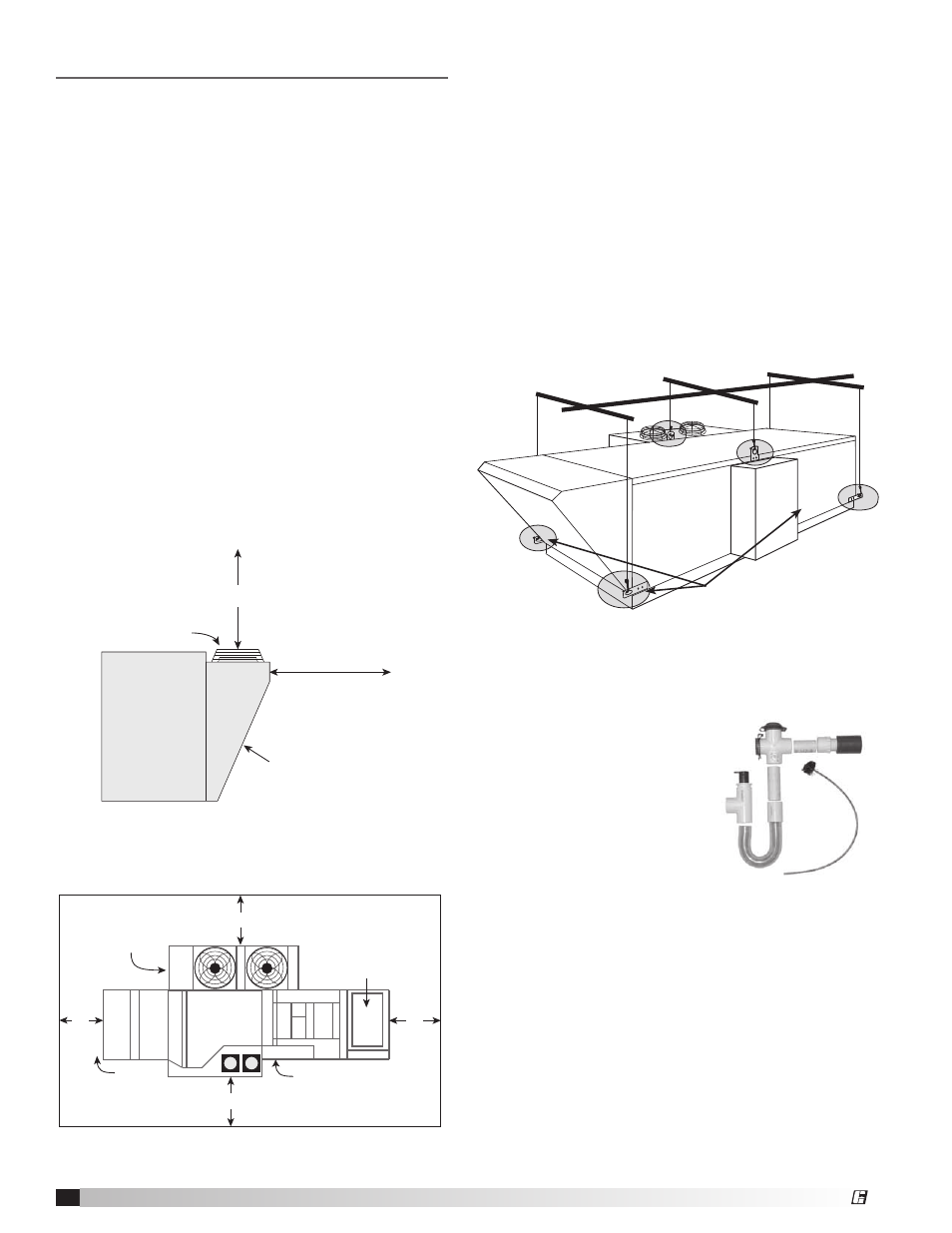
Use lifting lugs on
all four corners.
Lifting Details
Lifting
All units equipped with this module are provided with
either four or six lifting lugs. When the unit is being
hoisted, all of the provided lugs must be used for
support. Four lifting lugs are on the four corners of
the unit, located at the base. In addition, there may be
two more lifting lugs located at the top of the unit. The
locations of those two top lugs varies somewhat from
unit to unit.
Use spreader bars as shown to prevent damage to the
cabinet. If top-mounted lifting lugs are present, they
must be used in conjunction with the bottom-mounted
lifting lugs when hoisting the unit.
Install Condensate Drain (P Trap)
The only installation step that
is specific to the DX module is
installation and priming of the
engineered P trap. Locate the
P trap kit that was shipped with
the unit and install the kit in
accordance with the enclosed
instructions.
®