Pre-starting checks, Commercial kitchen installation, Dimensional data – Greenheck USGF (462077) User Manual
Page 6: Kitchen roof mounting installation, Usgf - dimensional data, Warning
6
Model USGF Ultimate Steel Grease Fan
®
NEMA 3R
Disconnect
factory wired
from motor to
disconnect
through the
breather tube
(Optional)
Liquid Tight
Flexible Conduit
by Others
Recommended
Roof Opening
Roof Deck
Minimum 40 in.
(1016 mm)
Discharge
Height
8 in.
(203 mm)
minimum
Grease
Trap
Vented Curb
Hinged Curb Cap
Extension
External Wiring
Welded Duct
by others
minimum of
18 in. (457
mm) above
roof deck per
NFPA
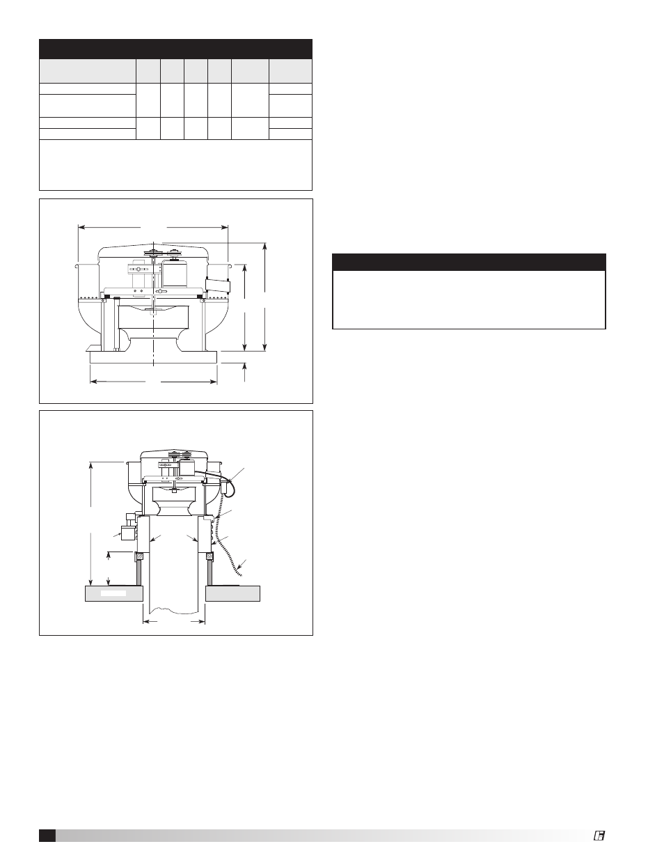
Commercial Kitchen Installation
Traditional External Grease Drain
Figure 12
Dimensional Data
Figure 11
B
1¾ in. (44 mm)
A
D
C*
Kitchen Roof Mounting Installation
Note: UL/cUL 762 Installation are for Restaurant
Applications
1. The size of the duct must be equal or larger than inlet
opening.
2. Secure the fan to curb according to details on pages
4 and 5.
3. Use grease trap, hinge kit and external junction box.
4. Area codes may require a continuous weld between
duct and inlet.
5. To comply with NFPA 96 the fan discharge has to
be a minimum 40 inches (1016 mm) above the roof
surface and a minimum of 10 feet (3048 mm) from
any building air intake and be a minimum exhaust
velocity in the duct should be 500 feet per minute.
6. Ductwork to an upblast discharge exhaust fan
is constructed of carbon steel not less than 16
MSG (1.6 mm) and extend a minimum of 18 inches
(457 mm) above the roof surface.
7. A grease trap is an aluminum trap designed to collect
grease residue to avoid drainage onto roof surface. It
contains a built‑in water separating baffle.
8. Regular inspection of the grease trap is
recommended. Depending on the amount of grease
discharged through the fan, the grease trap should
be changed accordingly to ensure proper operation.
Pre-Starting Checks
1. Check all fasteners and setscrews for tightness. The
wheel should rotate freely and be aligned as shown
in figure 14.
2. Wheel position is preset and the unit is test run at the
factory. Movement may occur during shipment and
realignment may be necessary.
3. Centering can be accomplished by loosening the
bolts holding the drive frame to the shock mounts
and repositioning the drive frame.
4. Wheel and inlet cone overlap can be adjusted by
loosening the setscrews in the wheel and moving the
wheel to the desired position.
5. Fan RPM should be checked and verified with a
tachometer.
6. Direction of wheel rotation is critical. Reversed
rotation will result in poor air performance, motor
overloading and possible burnout. If three‑phase
power, reverse any two of the three wires to switch
wheel rotatation.
7. Check wheel rotation (viewing from the shaft side) by
momentarily energizing the unit. Rotation should be
clockwise and correspond to the rotation decal on
the unit, see figure 13. If wheel rotation is incorrect
reverse two of the wiring leads or check motor wiring
for single‑phase.
WARNING
In a kitchen exhaust application do not use a
backdraft damper.
Note: In kitchen fan applications, exhaust upblast
fans must have external wiring.
USGF - Dimensional Data
Model
A
B
*C
D
Roof
Opening
*Approx.
Weight
USGF‑140, 140HP
26
(660)
28
7
⁄
8
(733)
29
3
⁄
4
(756)
19
3
⁄
8
(492)
18
1
⁄
2
(470)
125 (57)
USGF‑160, 160HP,
160XP
131 (59)
USGF‑180, 180HP
30
(762)
35
3
⁄
8
(899)
28
5
⁄
8
(727)
21
(553)
20
1
⁄
2
(521)
190 (86)
USGF‑200, 200HP
213 (97)
• All dimensions are in inches (millimeters). *Approximate weight shown in pounds
(kilograms)
is the largest cataloged Open Drip Proof motor and may vary depending on
motor size. Approximate weight does not include the roof curb.
• Dimension “A” is the inside dimension of the curb cap. The roof curb should be 1½ in.
(38 mm)
less than the curb cap to allow for roofing and flashing.
• Roof opening is a square dimension.