Inspection and maintenance during storage, Installation, General roof mounting installation – Greenheck USGF (462077) User Manual
Page 3: Typical wiring diagram, Warning
3
Model USGF Ultimate Steel Grease Fan
®
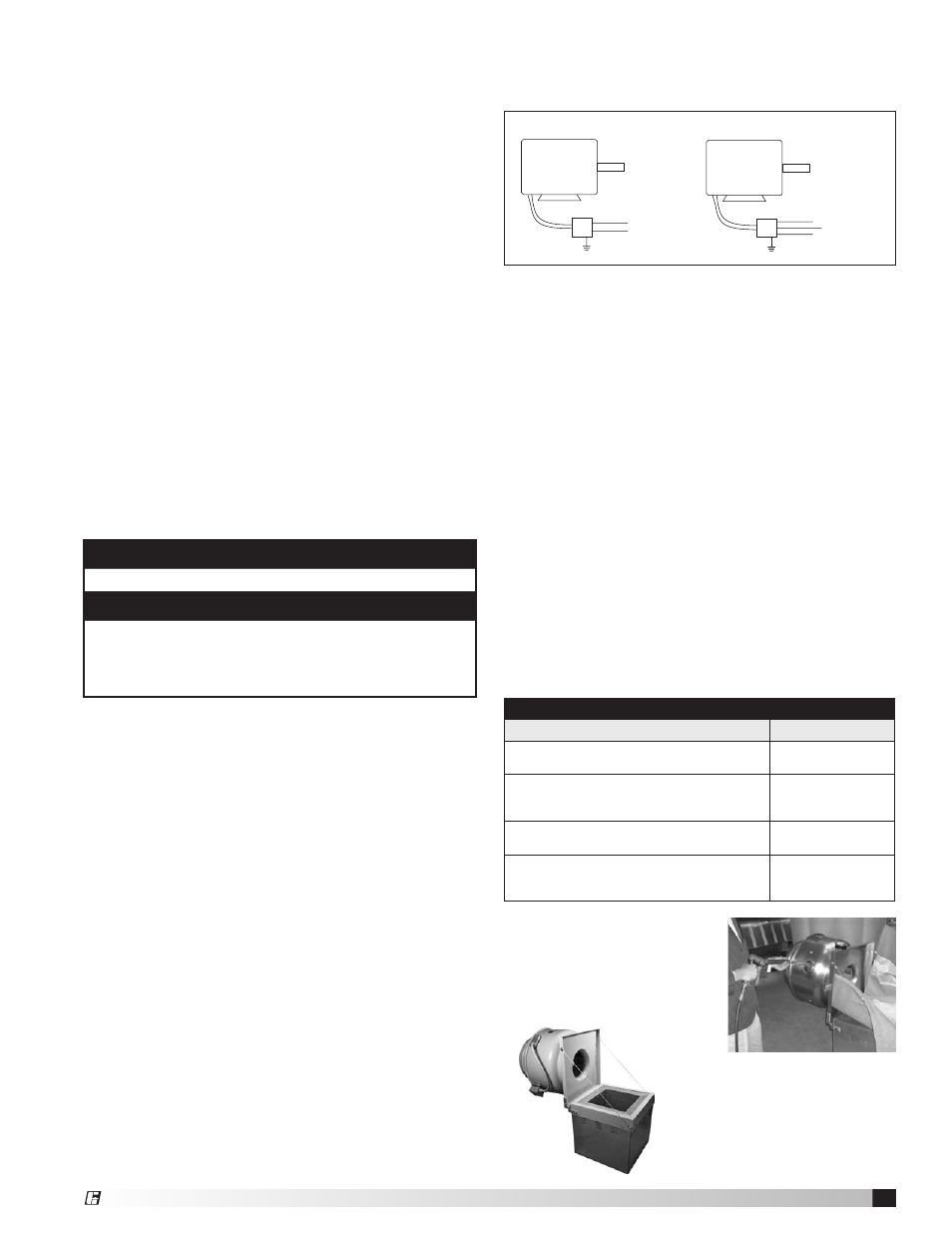
MOTOR
L1
115/208-230/60/1
208-230/460/60/3
MOTOR
J-BOX
J-BOX
SUPPLY VOLTAGE
SUPPLY VOLTAGE
L2
L1
L2
L3
Typical Wiring Diagram
Figure 3
WARNING
Disconnect power before installing or servicing.
WARNING
Installation, troubleshooting and parts replacement
is to be performed only by qualified personnel.
Consult and follow NFPA 96 recommendations.
NFPA 96 instructions supercede this document.
Table 1: Exhaust System Inspection Schedule
Type or Volume of Cooking
Frequency Check
Systems serving solid fuel cooking
operations
Monthly
Systems serving high‑volume cooking
operations, such as 24 hour cooking,
char broiling, or wok cooking
Quarterly
Systems serving moderate‑volume cooking
operations
Semiannually
Systems serving low‑volume cooking
operations, such as churches, day camps,
seasonal business, or senior centers
Annually
Fan wheels should be blocked to prevent spinning
caused by strong winds.
Inspection and Maintenance During
Storage
While in storage, inspect fans once per month. Keep a
record of inspection and maintenance performed.
If moisture or dirt accumulations are found on parts,
the source should be located and eliminated. At each
inspection, rotate the wheel by hand ten to fifteen
revolutions to distribute lubricant in motor and bearings.
If paint deterioration begins, consideration should
be given to touch‑up or repainting. Fans with special
coatings may require special techniques for touch‑up or
repair.
Machined parts coated with rust preventive should be
restored to good condition promptly if signs of rust
occur. Immediately remove the original rust preventive
coating with petroleum solvent and clean with lint‑free
cloths. Polish any remaining rust from surface with
crocus cloth or fine emery paper and oil. Do not destroy
the continuity of the surfaces. Thoroughly wipe clean
with Tectyl
®
506 (Ashland Inc.) or the equivalent. For hard
to reach internal surfaces or for occasional use, consider
using Tectyl
®
511M Rust Preventive,
WD‑40
®
or the
equivalent.
Installation
General Roof Mounting Installation
1. On the roof surface, cut an appropriate sized hole
and follow manufacturer’s instructions on curb
installation, refer to page 4. Caulk and flash the curb
to ensure a water tight seal.
2. Remove motor cover. Access to the motor
compartment is accomplished by removing the
screws as shown in figure 2. The cover can then
be removed and placed on a flat surface in an area
protected from strong winds.
3. On the drive frame use the lifting lugs to lift and
place the unit on top of roof curb. (Refer to figure 1
on page 2).
4. Secure fan to curb according to mounting details,
refer to page 5.
5. Verify power line wiring is de‑energized before
connecting fan motor to power source.
6. Connect power supply wiring to the motor as
indicated on the motor nameplate or terminal box
cover. Check the power source for compatiblity with
the requirements of your equipment.
7. Check fan wheel for free rotation and re‑center if
necessary.
8. Check all fasteners for tightness.
9. Mount and wire safety disconnect switch under
motor cover. Wire control switches at ground level,
refer to figure 3.
10. Replace motor cover.
11. For NFPA ‑ restaurant applications: the electrical
supply must enter the motor compartment through
the breather tube. For other non‑flammable
applications the electrical supply can be routed
throught the conduit chase between the curb cap
and the bottom of the motor compartment. Consult
local code authorities for specific requirements.
12. A drain trough is provided on all USGF fans for
single‑point drainage of water and residue. Some
means for collection of this residue must be
provided, either a container directly under the trough
or use of an adapter and pipe to carry the residue
to a remote collection point. An optional grease trap
with water separator baffles is available from your
Greenheck representative.
13. A Clean‑Out Port and hinging curb cap are also
provided on all USGF’s. They aid the cleaning
process through additional access to the wheel. The
USGF is designed for the worst cooking conditions,
such as char broilers, solid fuel cooking or oriental
cooking. Table 1 shows the suggested Exhaust
System Inspection Schedule published in NFPA 96.
14. Clean‑Out Port: Position
Clean‑Out Port so it is
on the side of unit when
hinged open, see figure 4.
Figure 4
Figure 5
15. Hinged Curb Cap: During
installation of the hinge curb
cap kit, it is important not to
allow the fan to go beyond
90º, see figure 5.