Prestart-up checks, Non-ducted installation, Duct connections – Greenheck EQB (479049) User Manual
Page 4
Mixed Flow Inline Fan
4
6. The adjustable motor pulley is factory set for
the RPM specified. Speed can be increased by
closing or decreased by opening the adjustable
motor sheave. Two groove variable pitch pulleys
must be adjusted an equal number of turns open
or closed. Any increase in speed represents a
substantial increase in the horsepower required
by a unit. Motor amperage should always be
checked to avoid serious damage to the motor
when speed is varied.
4. Check for bearing alignment and lubrication.
5. Check the pulleys for proper alignment.
Misaligned pulleys lead to excessive belt wear,
vibration, noise, and power loss. (See Fig. 11).
Prestart-up Checks
1. Disconnect and lock-out all power switches to
fan.
2. Check all fasteners, set screws and locking
collars on the fan, wheel, bearings, drive, motor
base and accessories for tightness.
3. Rotate the fan wheel by hand and assure no
parts are rubbing. The wheel should rotate
freely and be aligned as shown in Fig. 10. Wheel
position is preset and the unit is tested at the
factory. Movement may occur during shipment,
and realignment may be necessary.
Radial Gap*
Adjust inlet cone position such that the radial gap
between the wheel cone and inlet cone is evenly
distributed around the wheel.
Alignment*
If necessary, adjust wheel position by loosening
the wheel hub from the fan shaft so that a
straight edge held tight to the wheel cone just
touches the inlet cone. Refer to Fig. 10.
*Note these functions must take place prior to
installation.
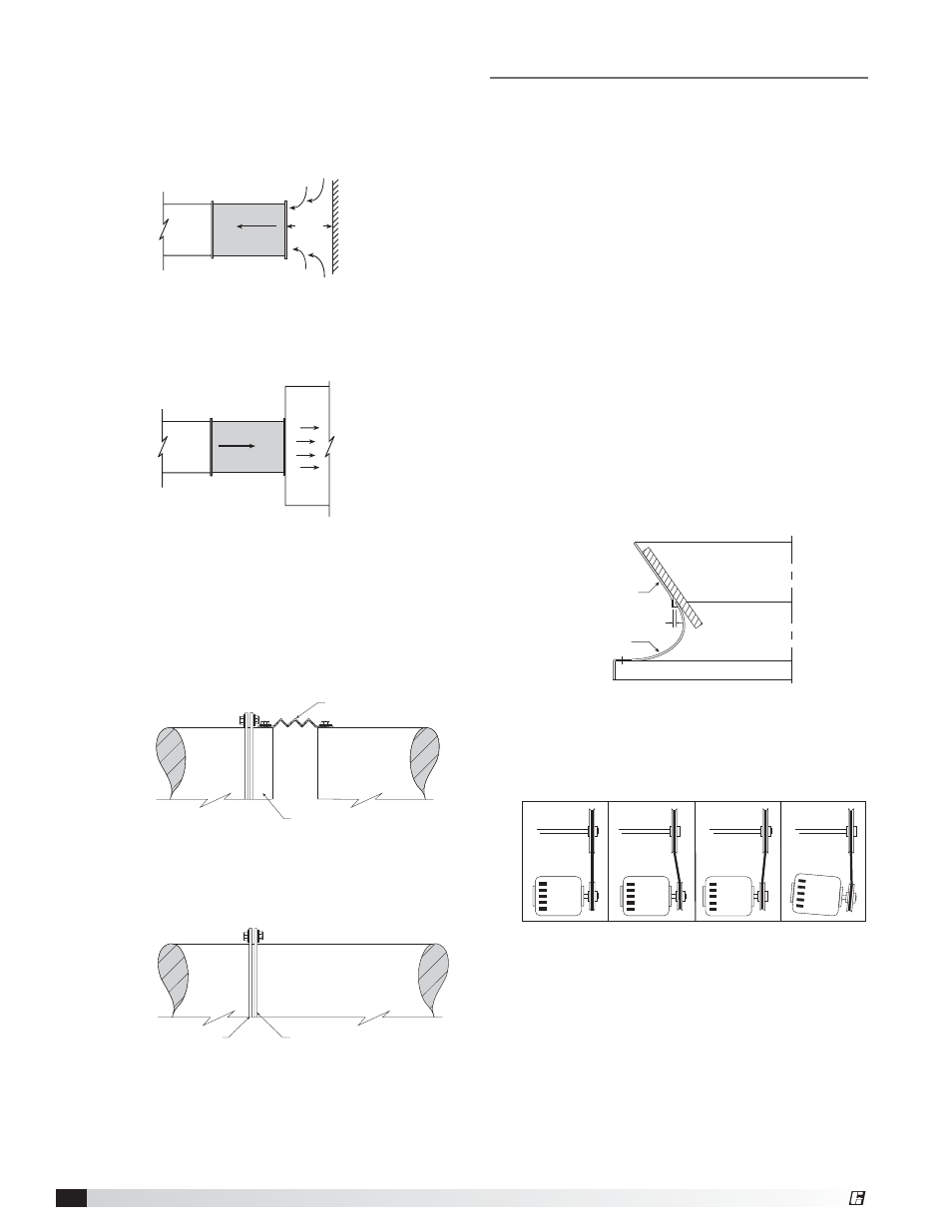
Non-Ducted Installation
Inlet Clearance – Installation of a fan with an open
inlet too close to a wall or bulkhead will cause
reduced fan performance. It is desirable to have a
minimum of one equivalent duct diameter between
the fan inlet and the wall.
1 Duct
Dia.
Free Discharge – Free or abrupt discharge into a
plenum results in a reduction in fan performance.
The effect of discharge static regain is not realized,
and performance is reduced.
Duct Connections
It is highly recommended to use a flexible sleeve
connection instead of a rigid duct connection. This will
reduce vibration transmission through the ductwork.
Slip-Fit End Connection - Removable duct collars
are bolted to the fan to provide a slip-fit connection
for a flexible sleeve.
Flexible Sleeve
Duct
Fan
Duct Collar
Flanged End Connection – Remove standard duct
collars to allow for flanged end connection. Directly
bolt inlet and outlet flanges to ductwork. No additional
parts are required.
Duct
Fan
Inlet/Outlet
Flange
Duct Flange
Fig. 6
Fig. 7
Fig. 8
Fig. 9
Wheel Cone
Inlet Cone
Gap
Fig. 10
Fig. 11
WRONG
CORRECT
WRONG
WRONG
®