Installation, Mounting configurations, Removing from storage – Greenheck EQB (479049) User Manual
Page 3: Ducted installations
Mixed Flow Inline Fan
3
C
A
B
A
C
B
Hanging Mount
Base
Mount
A
B
B
A
Base
Mount
Hanging
Mount
Removing From Storage
As fans are removed from storage to be installed
in their final location, they should be protected and
maintained in a similar fashion, until the fan equipment
goes into operation.
Prior to fully assembling and installing the fan and
system components, inspect the fan assembly to
make sure it is in working order.
1. Check fasteners, set screws, wheel, bearings,
drive, motor base and accessories for tightness.
2. Rotate the fan wheel by hand and assure no parts
are rubbing. Access to the wheel is obtained
through the inlet of the fan.
3. Ensure proper wheel settings for radial gap and
alignment. See Fig. 10 on page 4.
Installation
Installations with poor inlet or discharge
configurations may result in reduced fan performance.
See Fig. 4 thru 7.
Ducted Installations
Inlet Duct Turns – Installation of a transition or
duct turn too close to the fan inlet reduces fan
performance. Restricted or unstable flow at the fan
inlet can cause pre-rotation of incoming air or uneven
loading of the fan wheel, yielding large system losses
and increased sound levels. To achieve full fan
performance, there should be at least one equivalent
duct diameter between the transition or duct turn and
the fan inlet.
Discharge Duct
Turns – Fan
performance is
reduced when
transitions or duct
turns are made
immediately after
the fan discharge.
To achieve
cataloged fan
performance there
should be at least three equivalent duct
diameters of straight ductwork between
the fan discharge and any duct turns or transitions.
Good
Poor
3 Duct
Diameters
Mounting Configurations
Fig. 1
Fig. 2
Good
Poor
Turning
Vanes
1 Duct
Dia.
Fig. 4
Fig. 5
Horizontal Hanging or
Base Mount
With a hanging mount, the
motor may be located on
either the top or bottom
of the housing. Base
mounting allows the motor
to be located on top only.
In these configurations,
standard mounting
supports are provided.
Refer to Table 1 for
dimensions.
Horizontal Hanging or
Base Mount
The motor may be
located on either side
of the housing with
a horizontal hanging
or base mount. In
these configurations,
extended mounting
supports are provided.
Refer to Table 1 for
dimensions.
TABLE 1
Model
A
B
C
EQB 12
18
3
⁄
8
(467)
25
1
⁄
8
(638)
27
3
⁄
4
(705)
EQB 15
22
1
⁄
8
(562)
27
5
⁄
8
(702)
33
1
⁄
2
(851)
EQB 18
26
5
⁄
8
(676)
31
5
⁄
8
(803)
38
(965)
EQB 22
31
3
⁄
4
(806)
37
5
⁄
8
(956)
44
1
⁄
2
(1130)
EQB 27
38
1
⁄
2
(978)
43
5
⁄
8
(1108)
52
(1321)
EQB 30
44
1
⁄
2
(1130)
50
5
⁄
8
(1286)
58
7
⁄
8
(1495)
Hanging
Mount
Base
Mount
E
D
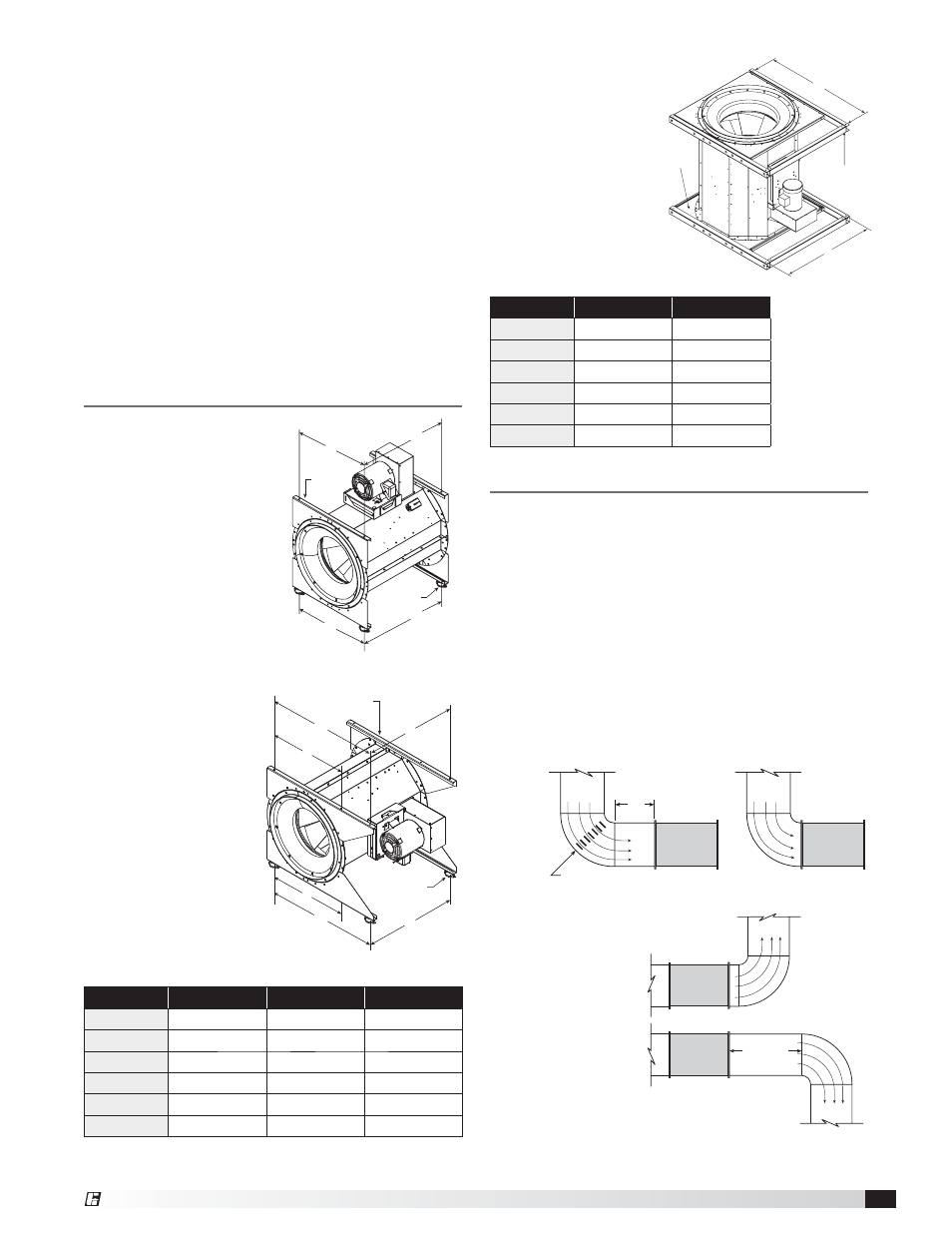
TABLE 2
Model
D
E
EQB 12
27
3
⁄
4
(705)
26
(659)
EQB 15
33
1
⁄
2
(850)
29
5
⁄
8
(752)
EQB 18
38
(965)
33
7
⁄
8
(860)
EQB 22
44
7
⁄
8
(1140)
39
5
⁄
8
(1006)
EQB 27
52
(1320)
46
1
⁄
8
(1172)
EQB 30
58
7
⁄
8
(1496)
50
7
⁄
8
(1291)
Vertical Mount
With a vertical mount,
the unit can either be
hung from above, or
mounted to the floor.
The motor will always
be mounted on the side
of the unit between the
mounting supports.
Refer to Table 2 for
dimensions.
Fig. 3
®