Start-up — direct gas, Unit control center, Burner and baffles – Greenheck DGK (468695) User Manual
Page 9: Direct gas nameplate
9
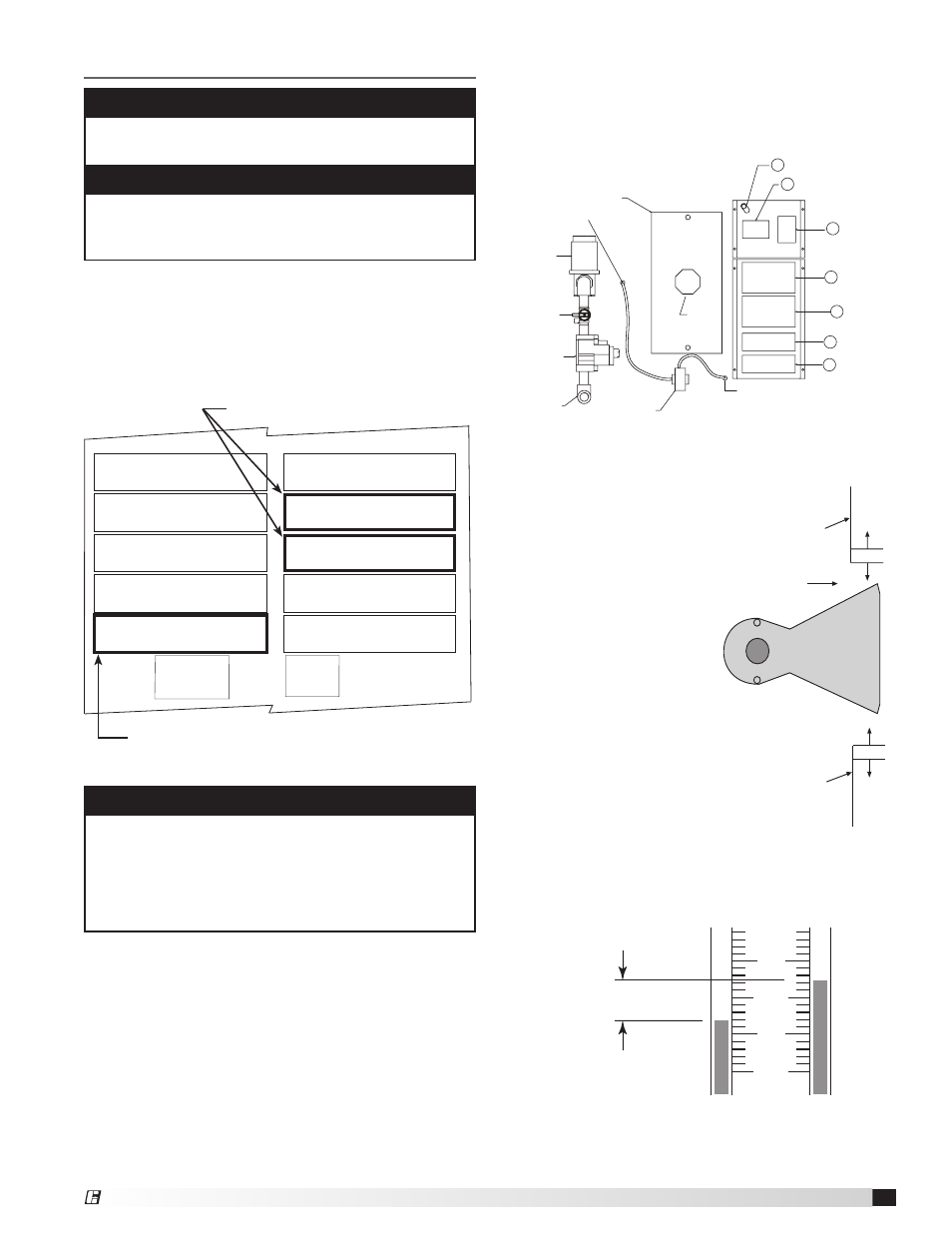
Start-Up — Direct Gas
ACCESS PANEL TO:
• BURNER,
• SPARK ROD
• FLAME ROD
AIRFLOW SWITCH
INLET AIR SENSOR
HIGH LIMIT
AMPLIFIER
IGNITION CONTROL
CONTACTOR
GOUNDING LUG
TRANSFORMER
BURNER MANUAL
SHUTOFF VALVE
COMBINATION
SHUT-OFF
VALVE/REGULATOR
GAS CONNECTION
MODULATING
VALVE
AIRFLOW TAP
AIRFLOW TAP
BURNER
VIEWPORT
1
2
3
4
6
7
8
5
Unit Control Center
2. Set the Burner Air Pressure Differential: With all
filters, the blower access door in place, and the fan
running and discharging 70ºF air, connect a U-Tube
manometer to the airflow taps (inside the unit control
center) and measure the static pressure across the
burner.
IMPORTANT
Proper air velocity over the burner is critical on
direct fired gas units. If the air velocity is not within
the unit specifications, the unit will not operate
efficiently, may have sporadic shutdowns and may
produce excessive carbon monoxide (CO) or other
gases.
IMPORTANT
For proper unit function and safety, follow the start-up
procedure in the exact order that it is presented.
IMPORTANT
This start-up should begin after all of the installation
and the Blower Start-Up procedures have been
completed.
The proper static pressure should be between 0.625
and 0.675 in. wg. (see diagram
below). If needed, evenly adjust
the baffles above and below
the burner, keeping the burner
centered in the opening until
the required pressure is
obtained.
The pressure drop was set
at the factory and may not
need adjustment.
This process may need
to be repeated until
the proper pressure is
achieved. This adjustment
will change the air
quantity delivered by the
unit and therefore the air
quantity delivered should
be rechecked. Refer to the
Blower Start-Up section.
To increase the static
pressure, decrease the opening. To decrease the
static pressure, increase the opening.
9
8
7
6
0.625 - 0.675 in. wc
Proper Static Pressure Reading
Adjustable
Top Baffle
Airflow
Burner
Adjustable
Bottom Baffle
Burner and Baffles
1. Check the Supply Gas Pressure: Check the
supply gas pressure and compare it with the unit’s
nameplate pressure requirements. Adjust the supply
regulator as needed until the supply gas pressure is
within the specified range. The nameplate is located
on the outside of the unit on the control panel side.
Direct Gas Nameplate
“ W.C.
“ W.C.
“ W.C.
F
PSI
“ W.C.
“ W.C.
MAX BTU/HR
BTU/H MAX
NORMAL MANIFOLD
PRESSURE
PRESSION DÕADMISSION
NORMALE
MIN GAS
PRESSURE
PRESSION DE GAZ
MIN BURNER
PRESSURE DROP
PERTE MIN DE PRESSION
DANS LE BRULEUR
TYPE OF GAS
NATURE DU GAZ
MIN BTU/HR
BTU/H MIN
MIN GAS PRESSURE
FOR MAX OUTPUT
PRESSION DE GAZ MIN
POUR PUISSANCE MAX
MAX BURNER
PRESSURE DROP
PERTE MAX DE PRESSION
DANS LE BRULEUR
MAX GAS
PRESSURE
PRESSION DE GAZ
MAX
DESIGN ∆T
∆T NORMALE
EQUIPPED FOR
CONCU POUR
SCFM
“ W.C.
EXTERNAL STATIC PRESSURE
PRESSION STATIQUE EXTERIEURE
AGAINST
CONTE
Minimum and maximum gas
pressures for maximum output
Type of gas
Model DGK Make-Up Air
®