Reference – Greenheck DGK (468695) User Manual
Page 19
19
1. Control Board - Provides mounting for the
controls.
2. Supply Motor Starter - 24 volt magnetic contacts
for starting supply motor.
3. Supply Overload - Provides electronic overload
protection to supply motor.
4. Low Voltage Transformer - 75 VA transformer
that provides low voltage to fan/starter controls
and optional inlet damper.
5. Air Proving Switch - Monitors the airflow to ensure
proper combustion.
6. Purge Timer - Initiates 10 second prepurge before
lighting the burner.
7. Low Voltage Transformer - 75 VA transformer
that provides low voltage to the heat controls.
8. Inlet Air Sensor - Outdoor air stat that
automatically controls the heating based on
outdoor air temperature.
9. Flame Safeguard/Spark Generator - Monitors
flame, shuts down unit when unsafe conditions are
detected.
10. Amplifier - Controls modulating valve, assures the
desired temperature is delivered.
11. Heat Relay - Allows amplifier to modulate the
modulating gas valve.
12. High Limit (not pictured) - Disc shaped component
located in the upper right hand corner of the
control center. Prevents the unit from discharging
air above a fixed set point of 120ºF.
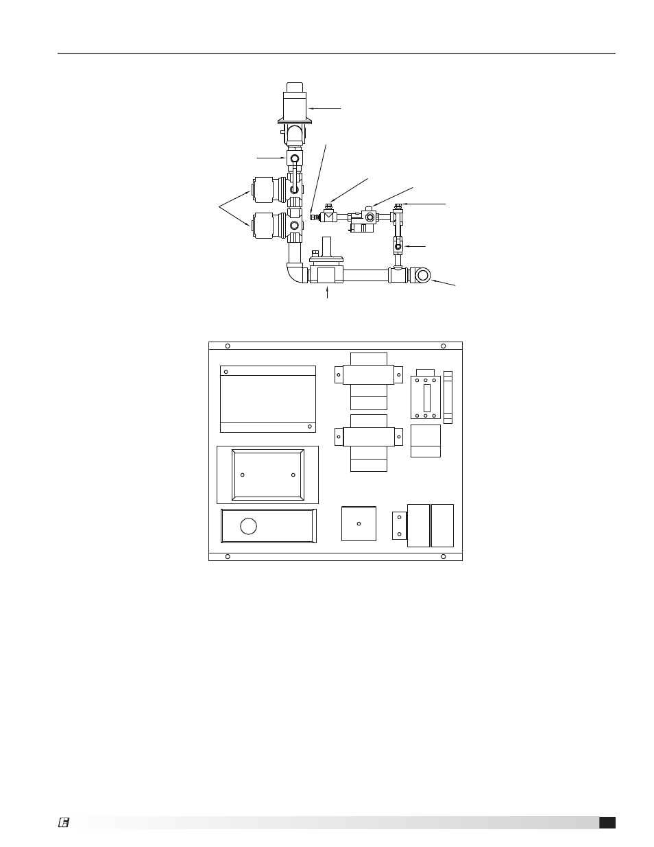
Reference
Typical DGK-H25 Gas Train Layout – Less than 800 MBH
Gas Connection
Regulator
Pilot Manual Shut-Off Valve
Safety Shut-Off Valves
Burner Manual Shut-Off Valve
Modulating Valve
Pilot Valve/Regulator
Pilot Test Port
Pilot Connection to Burner
Typical DGK-H25 Gas Train Layout - Less than 800 MBH
Supply Gas Pressure Test Port
Typical DGK-H25 Control Center Layout
DGK-H25 Control Center Layout
1
2
3
5
6
7
8
9
10
4
11
Model DGK Make-Up Air
®