Product overview – Grandstream GXV3501 Series User Manual User Manual
Page 7
GXV3501/GXV3504 Digital Video Server
Firmware 1.0.4.6 Page 7 of 36
Grandstream Networks, Inc. 09/2010
Product Overview
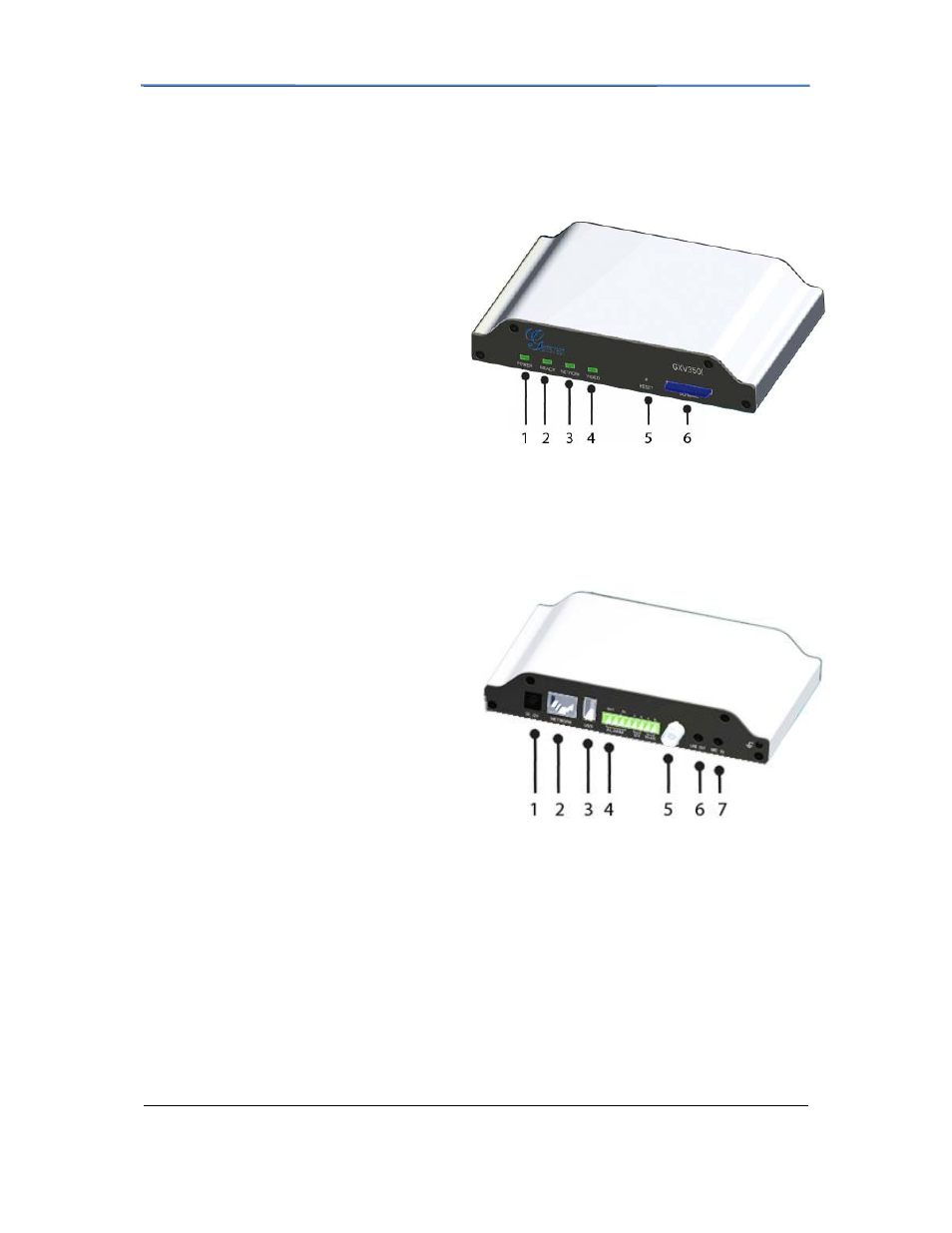
GXV3501Front Panel
1 POWER
–
The indicator will keep
green
if the power is on.
2 READY
–
The indicator will light up
green
if the device is ready.
3 NETWORK
–
The indicator will
flash
green
if there is data transmission with
the internet or stay
solid green
if there
is no data transmission.
4 VIDEO
–
The indicator will light up
green
when there is video input.
5 RESET
-
Press the Reset button for 6
seconds to perform a factory reset.
6 SD/MMC
– The SD/MMC slot.
GXV3501Back panel
1 DC 12V
– 12V DC power port; UL
Certified.
2 NETWORK
– 10/100 Switch LAN port
for connecting to Ethernet.
3 USB
– USB port for flash / hard drives.
Includes hot-swap support.
4 ALARM IN
– 1 Alarm Input port for
alarm equipment, ie. Infrared detector.
ALARM OUT – 1 Alarm Input port for
detectors, ie. Sirens.
VG – 12V DC power output port for other devices.
RS-485
– 1 PTZ connector.
5 VIN
– 1 BNC (Voltage: 1.0V p-p, Resistance 75Ω) port for video input3.5mm port for audio
output devices, ie. Speakers.
6 LINE OUT
– 3.5mm port for audio output devices, ie. Speakers.
7 MIC IN
– 3.5mm port for audio input devices, ie. Microphones.