Delta 31-735 User Manual
Page 12
12
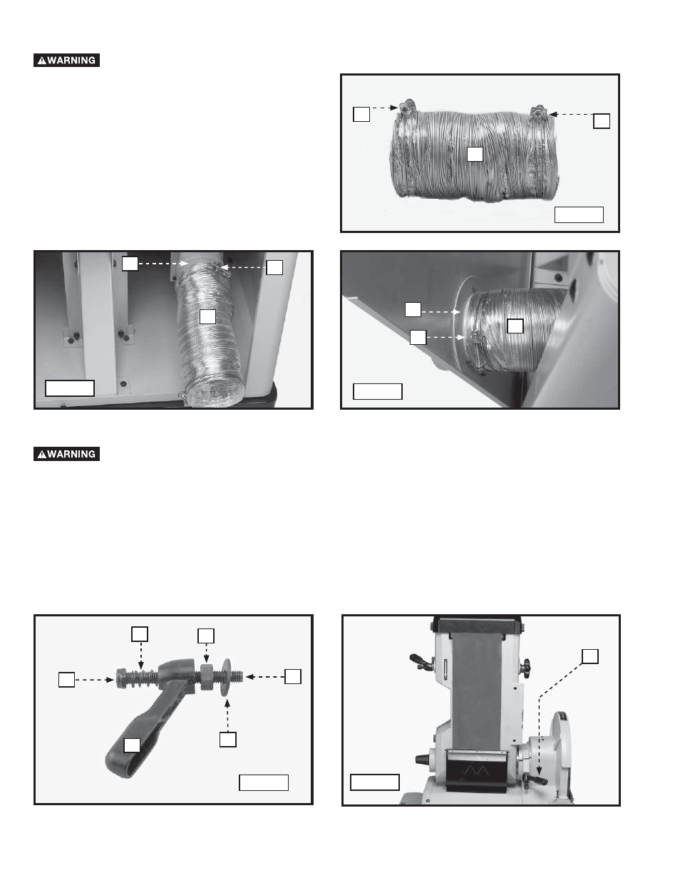
1. Place a hose clamp (A) Fig. 20 on each end of the
out-take hose (B).
2. Slide one end of hose (B) Fig. 21 over the dust
collector out-take port (C) and secure it with the
hose clamp (A).
3. Slide the other end of the hose (B) Fig. 22 over the
dust chute (D) on the inside of the back panel of the
cabinet. Secure it with the hose clamp (A).
4. Replace the back panel of cabinet that was removed
in STEP 2 of the section “INSTALLING THE DUST
BAFFLE”.
INSTALLING THE DUST COLLECTOR OUT-TAKE HOSE
Disconnect the machine from the power source!
A
B
A
Fig. 20
Fig. 21
Fig. 22
C
A
B
B
D
A
BELT SANDER TABLE
1. Thread a 3/8-16 lock nut (A) Fig. 23 on a 3/8-16 x 3-1/2" stud (B).
NOTE: Thread the lock nut (A) FIG. 23 flush or slightly below the threads on the stud.
2. Place a 1-3/16" spring (C) Fig. 23 on the stud (B).
3. Insert the sanding ratchet lever (D) Fig. 23 on the stud (B).
4. Thread a 3/8-16 hex nut (E) Fig. 23 on the stud (B).
5. Place a 3/8" flat washer (F) Fig. 23 on the stud (B).
6. Loosen the ratchet lever (H) Fig. 24.
7. Raise the belt sander to the the horizontal position (Fig. 24).
8. Tighten the lock knob (H) Fig. 24.
Disconnect the machine from the power source!
Fig. 23
Fig. 24
A
B
C
D
E
F
H