Assembly instructions – GAMMA 6004 STRINGING MACHINE 2 POINT SC MOUNTING (Issue 5C - February 2014) User Manual
Page 5
5
ASSEMBLY INSTRUCTIONS
Base Leg Assembly
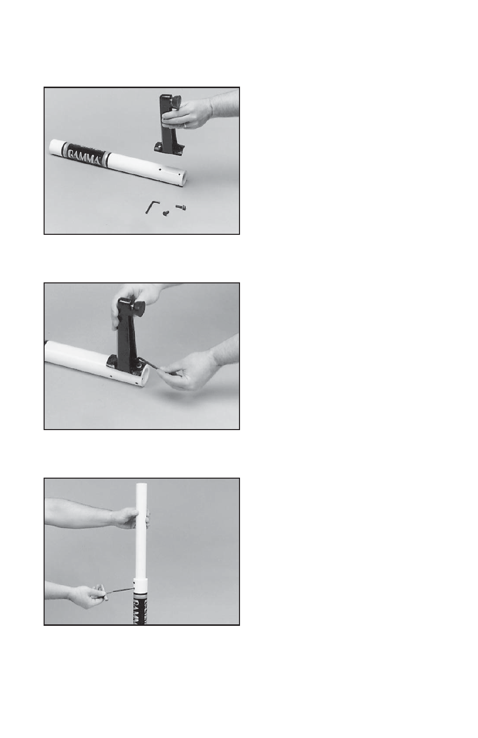
The stringing machine uses a four leg base
design. The legs must be assembled to the
lower column support before use. This is
the larger of the two posts with the GAMMA
label. Align the holes in the leg fl ange with
the matching holes in the lower column
support post.
Secure the leg with one FLAT HEAD cap
screw through the upper hole, and one
SOCKET HEAD cap screw through the
bottom hole. Repeat this procedure for the
three remaining legs.
Base Foot Height Adjustment
Each foot of the Base Stand can be adjusted
to compensate for uneven surfaces.
Upper Column Support Assembly
The upper column support is shipped inside
of the lower column support. Unloosen the
two set screws at the top of the lower column
support / base leg assembly. Extend the up-
per column to the maximum height and lock
in place with the two set screws located at
the top of the lower column support.
- 6004 STRINGING MACHINE 2 POINT SC MOUNTING (Issue 3 - September 2010) 5003 STRINGING MACHINE 6 POINT SC MOUNTING (Issue 10A - Febryary 2014) 5003 STRINGING MACHINE 2 POINT SC MOUNTING (Issue 5B - February 2014) 5003 STRINGING MACHINE 6 POINT SC MOUNTING (Issue 4A - February 2014) 5003 STRINGING MACHINE 6 POINT SC MOUNTING (Issue 1 - April 2010) 5003 STRINGING MACHINE 2 POINT SC MOUNTING (Issue 2 - December 2009) PROGRESSION STII STRINGING MACHINE (Issue 7A - February 2014)