Chapter 2 installation instructions – Foxconn NF4K8AC-RS User Manual
Page 23
16
Chapter 2 Installation Instructions
This motherboard includes connectors for FDD, IDE devices, SATA devices,
USB devices, IR module, CPU fan, system fan, and others.
Floppy Connector: FLOPPY
This motherboard includes a standard floppy connector, supporting 360 K, 720 K,
1.2 M, 1.44 M, and 2.88 M FDDs.
HDD Connector: IDE1&IDE2
These connectors support the provided UltraDMA 133/100/66/33 IDE hard disk
ribbon cable. Connect the cable’s blue connector to the primary (recommended)
or secondary IDE connector, then connect the gray connector to the UltraDMA
133/100/66/33 slave device (hard disk drive) and the black connector to the
UltraDMA 133/100/66/33 master device. If you install two hard disks, you must
configure the second drive as a slave device by setting its jumper accordingly.
Refer to the hard disk documentation for the jumper settings.
Other Connectors
Attention:
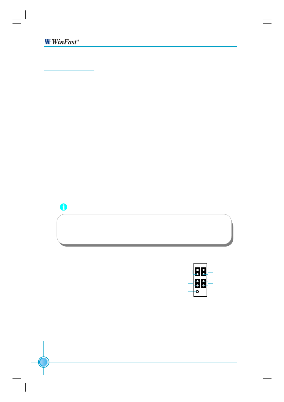
Front Panel Connector: JFP1
Attach the power LED, IDE LED, reset switch
and power switch connectors to the corre-
sponding pins.
Hard Disk LED Connector (IDELED)
Attach the connector to the IDELED on the front panel of the case; the LED will
flash while the HDD is in operation.
Reset Switch (RESET)
Attach the connector to the Reset switch on the front panel of the case; the
system will restart when the switch is pressed.
Ribbon cables are directional, therefore, make sure to always con-
nect with the cable on the same side as pin 1 of the PIDE/SIDE or
FLOPPY connector on the motherboard.
JFP1
NC
IDE_LED
RESET
PLED
PWRBTN#
1
+
-
+
-