Chapter 1 product introduction, Motherboard layout – Foxconn 761GXK8MC-RS User Manual
Page 11
Chapter 1 Product Introduction
4
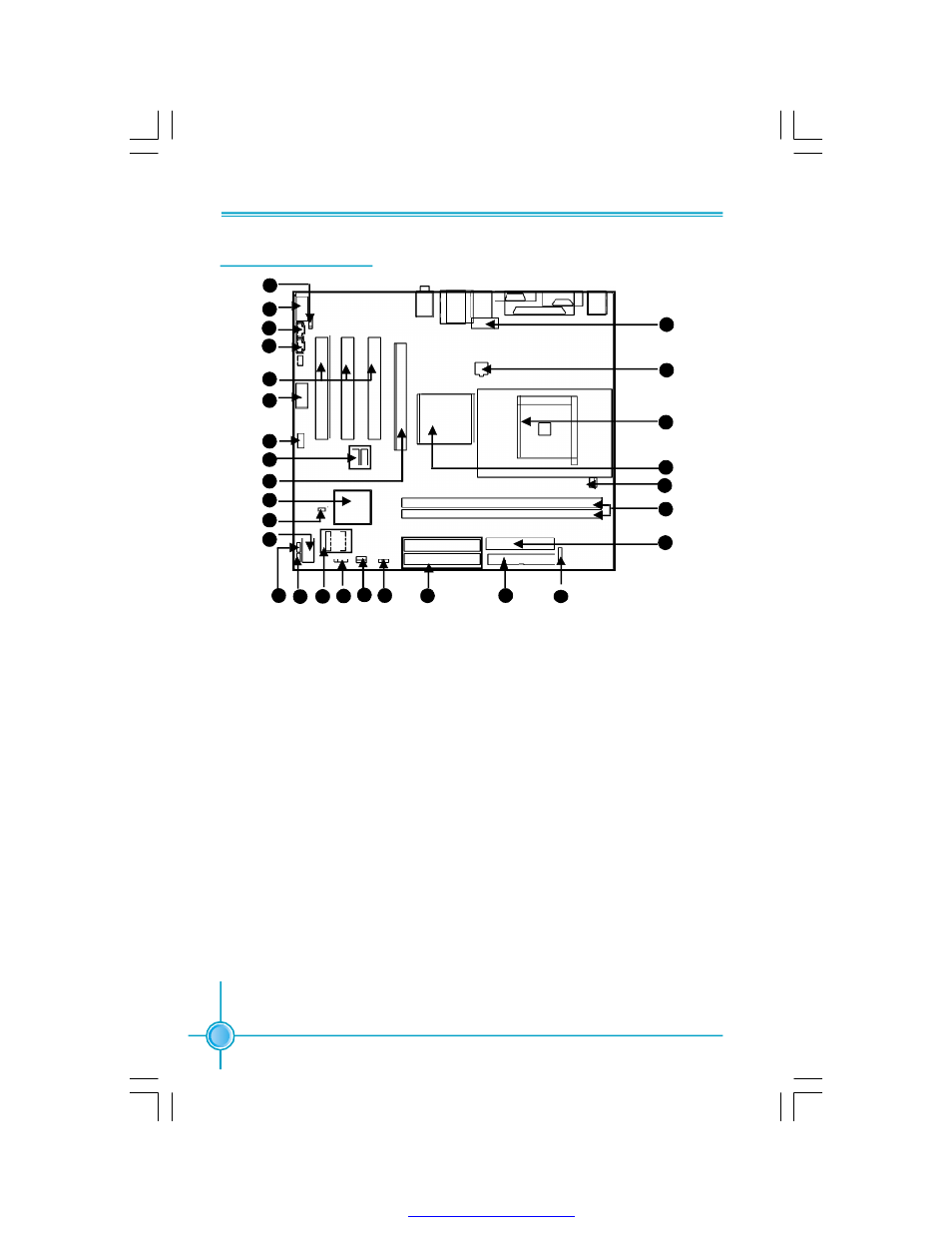
Motherboard Layout
1. S/PDIF_OUT Connector
2. F_Audio Connector
3. AUX_IN Connector(optional)
4. CD_IN Connector
5. PCI Slots
6. COM2 Connector (optional)
7. Front 1394 Connector(optional)
8. Front USB Connectors
9. PCI Express x16 Slot
10.South Bridge: SiS 964 Chipset
11. INTR Connector
12. Front Panel Connector
13. BIOS Protection Jumper
14. BIOS TBL_EN Jumper
15. SATA Connectors
16. Speaker Connector
17. System Fan1 Connector
18. Clear CMOS Jumper
19. IDE Connectors
20. FDD Connector
21. IrDA Connector
22. ATX 24-pin Connector
23. DDR DIMM Slots
24. CPU_Fan Connector
25. North Bridge: SiS761GX
26. CPU Socket
27. ATX 12V Power Connector
28. Front 1394 Connector (optional)
Note:
The above motherboard layout is provided for reference only; please
refer to the physical motherboard.
11
12
1
2
3
4
5
6
7
8
9
10
16 17 18
19
20
22
23
25
26
27
28
13 14 15
21
24
6
PDF created with pdfFactory Pro trial version