Chapter 2 installation instructions, Usb connectors: f_usb 1, f_usb 2, f_usb 3, Fan connectors: cpu_fan, fan1, fan2 – Foxconn NF4K8AB-8EKRS User Manual
Page 26: Irda connector: ir
18
Chapter 2 Installation Instructions
NF4K8AB Series User Manual
Power LED Connector (PLED)
Attach the connector to the Power LED on the front panel of the case. The Power
LED indicates the power supply status. When the system is in S0 status, the
LED is on. When the system is in S1 status, the LED is blink. When the system
is in S3, S4, S5 status, the LED is off.
Power Switch Connector (PWRBTN#)
Attach the connector to the power button of the case. Pushing this switch allows
the system to be turned on and off rather than using the power supply button.
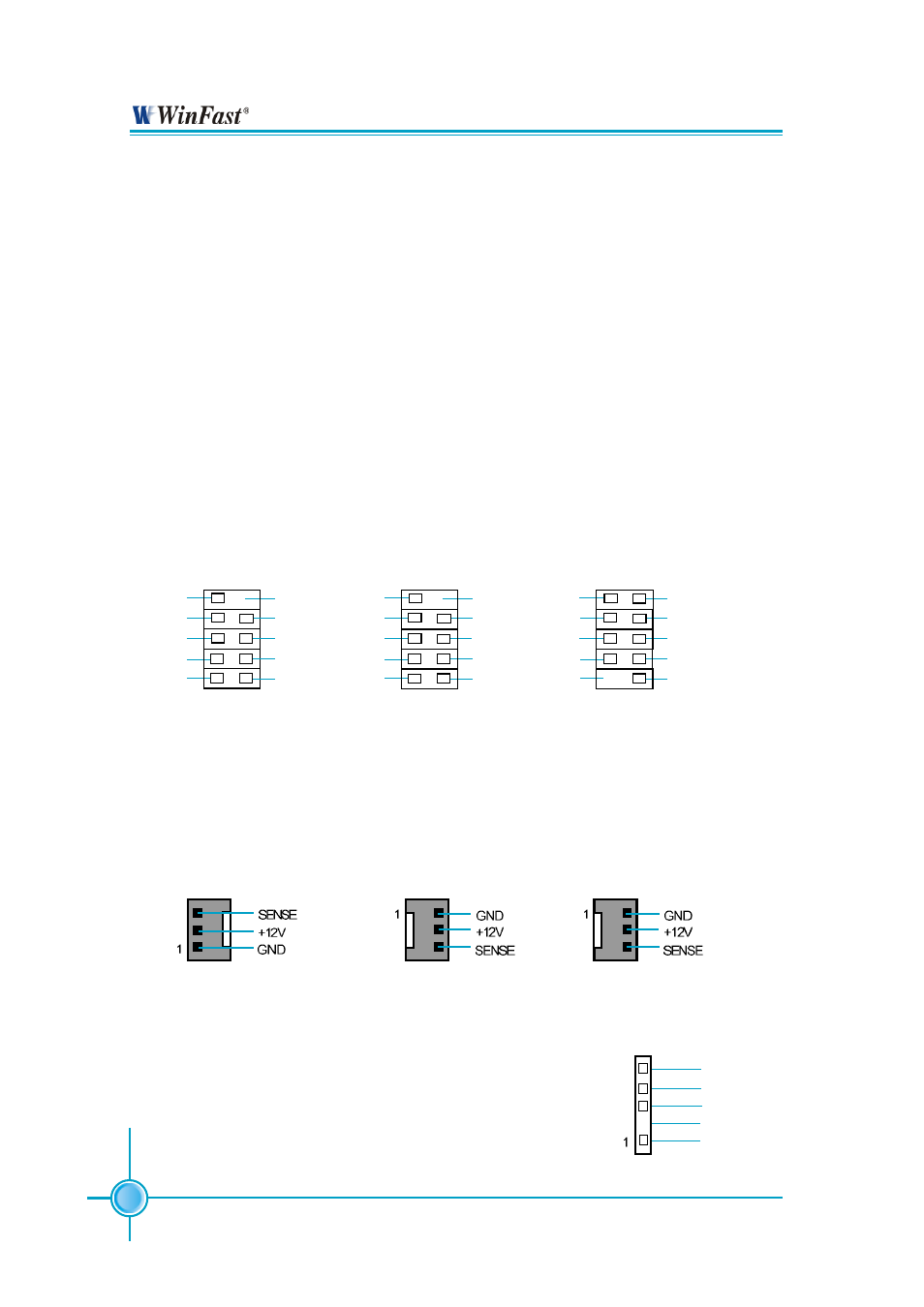
USB Connectors: F_USB 1, F_USB 2, F_USB 3
Besides four USB ports on the rear panel, the series of motherboards also
have three 10-pin headers on board which may connect to the front panel USB
cable to provide additional six USB ports.
FAN Connectors: CPU_FAN, FAN1, FAN2
Connect the CPU cooling fan cable into the 3-pin CPU_FAN on the motherboard.
Connect the chipset cooling fan cable into the 3-pin FAN1 on the motherboard.
Connect the system cooling fan cable into the 3-pin FAN2 on the motherboard.
F_USB1
D5+
D5-
Empty
GND
VCC
VCC
GND
D4-
D4+
2 1
NC
10 9
F_USB2
D7+
D7-
Empty
GND
VCC
VCC
GND
D6-
D6+
2 1
NC
10 9
F_USB3
D8+
GND
VCC
D8-
Empty
NC
D9-
GND
D9+
9 10
VCC
1 2
CPU_FAN
FAN1
FAN2
IrDA Connector: IR
The IrDA infrared transmission allows your computer
to send and receive data via an infrared ray. The rel-
evant parameters for the BIOS Integrated Peripherals
should be set prior to using this function.
IR
+5V
GND
IRRX
IRTX
Empty