Foxconn NF4K8AB-8EKRS User Manual
Page 25
17
Chapter 2 Installation Instructions
NF4K8AB Series User Manual
This motherboard includes connectors for FDD, IDE devices, SATA devices,
USB devices, IR module, CPU fan, system fan, and others.
Floppy Connector: FLOPPY
This motherboard includes a standard floppy connector, supporting 360 K, 720 K,
1.2 M, 1.44 M, and 2.88 M FDDs.
HDD Connectors: PIDE & SIDE
These connectors support the provided Ultra DMA133/100/66/33 IDE hard disk
ribbon cable and you can configure as a disk array through NVIDIA nForce4 IDE
RAID controller. Refer to chapter 5 for details on how to set up RAID configurations.
Connect the cable’s blue connector to the primary (recommended) or second-
ary IDE connector, then connect the gray connector to the slave device (hard
disk drive) and the black connector to the master device. If you install two hard
disks, you must configure the second drive as a slave device by setting its
jumper accordingly. Refer to the hard disk documentation for the jumper settings.
Other Connectors
Attention:
Ribbon cables are directional, therefore, make sure to always con-
nect with the cable on the same side as pin 1 of the PIDE, SIDE or
FLOPPY connector on the motherboard.
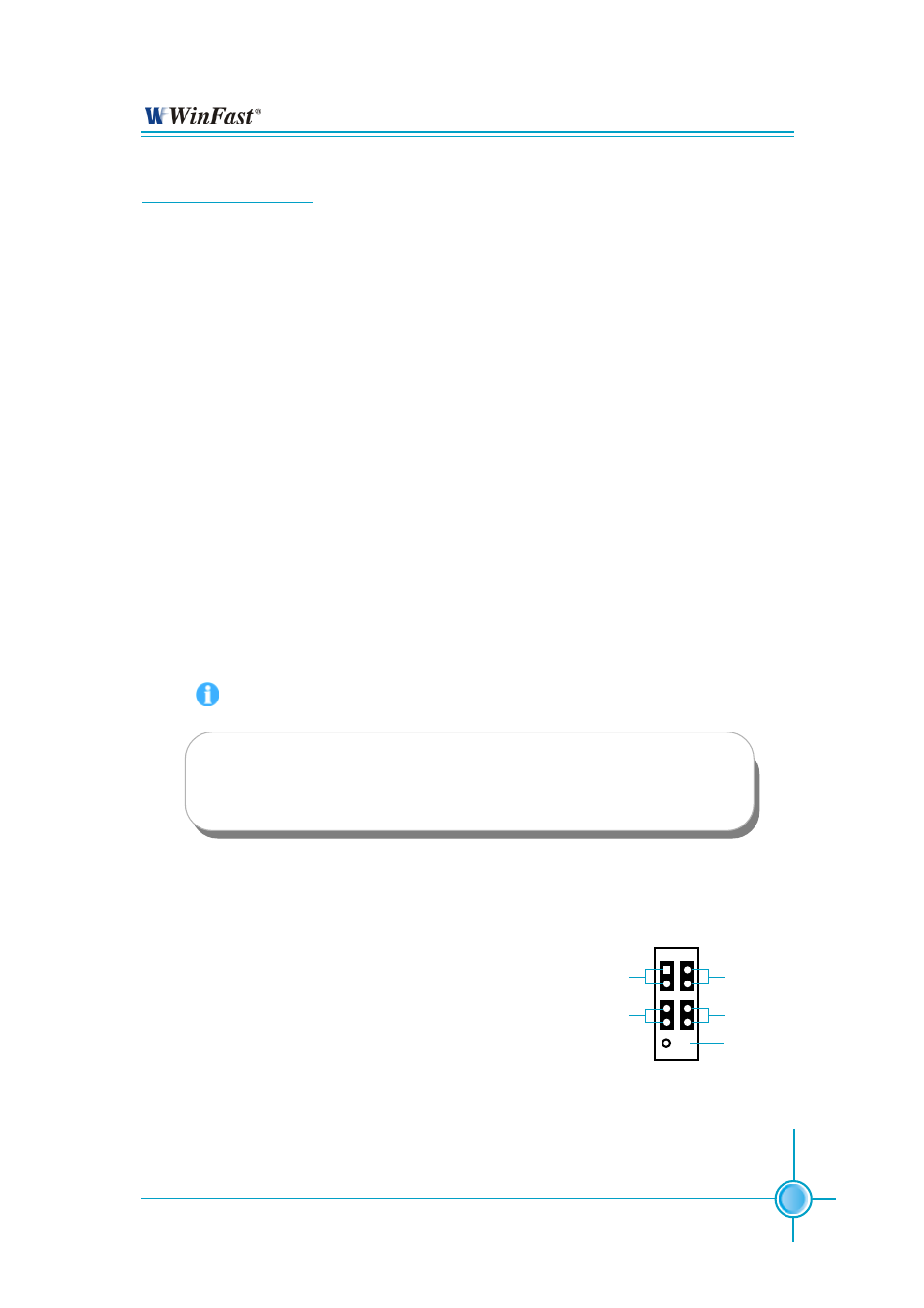
Front Panel Connector: FP1
This motherboard includes one connector for con-
necting the front panel switch and LED indicator.
Hard Disk LED Connector (IDE_LED)
Attach the connector to the IDE_LED on the front
panel of the case; the LED will flash while the HDD
is in operation.
Reset Switch (RESET)
Attach the connector to the Reset switch on the front
panel of the case; the system will restart when the
switch is pressed.
NC
IDE_LED
RESET
PLED
PWRBTN#
+ -
9 10
1 2
FP
FP1
!
+ -
Empty