0 general, 1 basic design, Worcester controls – Flowserve AF-17 Electronic Positioner User Manual
Page 3
WCAIM2031
AF-17 Electronic Positioner: Installation, Operation and Maintenance
3
1.0 GENERAL
1.1 Basic Design
The Worcester AF-17 Electronic Positioner was designed for use with the Worcester Series 75 actuators. However, it may also be
used with other actuators or electrically operated rotary devices, provided the specified load parameters as given in Part 6.3 are
not exceeded.
CAUTION: This positioner is sensitive to electrical noise; please see part 1.2.
PLEASE READ THIS SECTION
A. The AC AF-17 board 4-20 mA signal input circuit is protected with a 62 mA fuse (F1). The fuse is used to protect the input
circuit from an excessively high voltage. The fuse used in the input circuit is a Littlefuse PICO II very fast-acting fuse rated at 62
mA. There is a spare fuse located on the circuit board in the area of the large power resistors.
B. The AF-17 board is designed to receive a floating current input signal. This allows several pieces of equipment to be operated
from the same current loop while at the same time remaining electrically independent of each other.
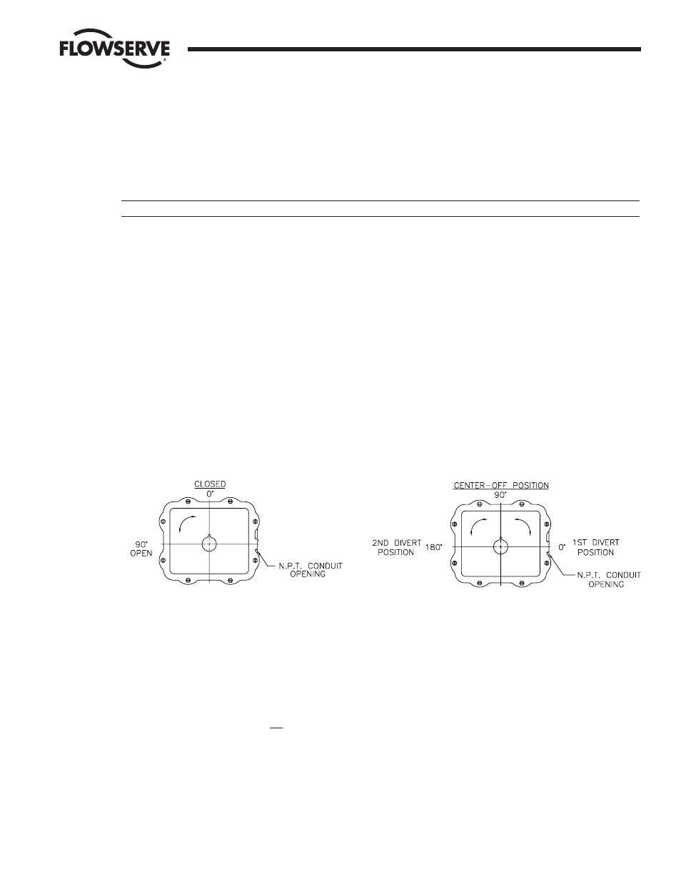
C. The AF-17 board can be set up in several ways for normal operation. The board is designed to control in 90° quadrants only.
The number of quadrants over which the board will control is determined by the number of teeth on the feedback pot pinion
gear. The adjustment trimpots on the board were not set up to reduce actuator travel for a 4-20 mA input span. For example,
trying to adjust the board such that 4 mA is closed and 20 mA is only 60% open is not possible with the standard set up.
The standard setups are:
1. 4 mA for full clockwise rotation, i.e., 0°, and 20 mA for full counter-clockwise rotation, i.e., 90° or 180°.
2. Split range where 4 mA would be full clockwise and 12 mA would be full counter-clockwise or 12 mA would be full clockwise
and 20 mA would be full counter-clockwise.
3. Each of the above standard setups can also be made reverse-acting.
Standard 90° Actuator
180° Center-Off Actuator
Series 75W, X, and Z Shown
Series 75W, X, and Z Shown typical
D. Quite often when we receive an actuator for repair at Flowserve we find that the only thing wrong with the unit is that the
feedback potentiometer is out of calibration. It is very important that the feedback pot be properly calibrated for correct
operation of the positioner board. It is also very important that the actuator shaft not be rotated out of the quadrant for which
the feedback pot has been calibrated. Whenever you have a problem with the positioner calibration, always check the feedback
pot calibration first. This must be done with no power applied to the circuit board. If the actuator is in the full clockwise
position, check the resistance between the purple and white/black potentiometer leads. The reading should be 80-90 ohms. If it
is not, rotate the face gear until the proper reading is achieved. If the actuator happens to be in the full counter-clockwise
position then check the resistance between the green and white/black potentiometer leads. If necessary, adjust the face gear for
an 80-90 ohm reading. NOTE: It is not necessary to loosen or remove face gear snap ring(s) to rotate gear; it is a friction fit.
Flow Control Division
Worcester Controls
Quadrants of Operation