1 dc motor actuator – Flowserve AF-17 Electronic Positioner User Manual
Page 22
7.0 APPLICATION NOTES
7.1 DC Motor Actuator
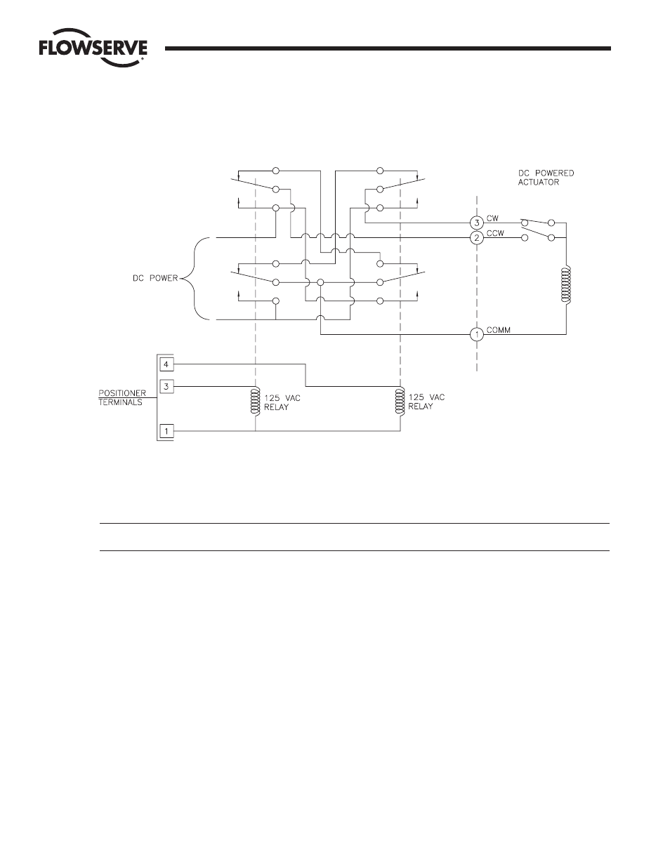
Typical wiring to operate DC motor actuators from Worcester AF-17 120 VAC electronic positioner. Terminal numbers in schematic
are for Worcester 75 actuators, but wiring arrangement is applicable to other makes. Relay contact ratings should be based on
switching a highly inductive load at the actuator’s maximum current rating (stalled current).
Motor is automatically braked when either relay goes from the “on” to the “off” position.
NOTE: The electronic brake on the positioner board should be made inoperative for this application (clip out U3 from circuit
board – See Figure 1 for location).
7.2 Bypass Switch for Manual Control (For 120 VAC Only)
This application is offered as a non-standard option through Flowserve’s Custom Products Department or may be altered by end
user. Figure 10 on the next page shows a schematic diagram of two switches for controlling the following functions:
One triple-pole, double-throw (TPDT) switch with center-off, switching from automatic to manual operation.
One single-pole, double-throw (SPDT) switch with center-off position for manually controlling clockwise (CW), counter-clockwise
(CCW) directions of actuator.
Figure 9
22
AF-17 Electronic Positioner: Installation, Operation and Maintenance
WCAIM2031
Flow Control Division
Worcester Controls