8maintenance and repair, 1 driver module assembly – Flowserve 3400MD Digital Positioner User Manual
Page 36
Logix 3400MD Digital Positioner FCD LGENIM3404-08-AQ –5/15
36
Definitions:
XDTB_MAIN - Main Transducer Block - Contains parameters used
mostly for command.
XDTB_TECH - Technician Transducer Block - Contains diagnostics
and uncommon setup parameters
XDTB_MD - MD Transducer Block - Contains the PRO diagnostic
parameters
R - Parameter is Readable
W - Parameter is Writeable
N - Parameter is Non-Volatile
S - Parameter is Static as defined by the Fieldbus Specification.
N/A - Not Applicable
c
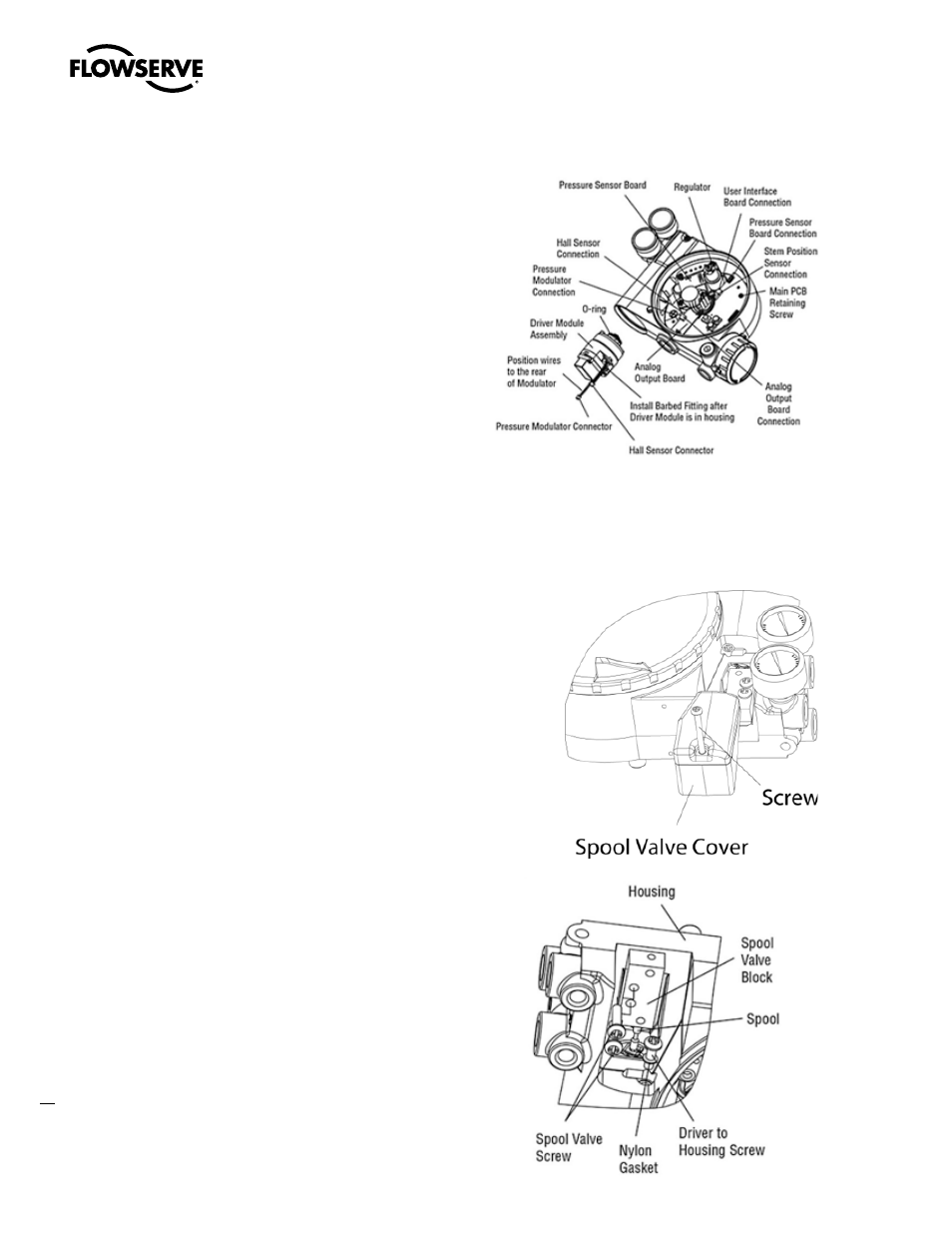
DANGER: Spool (extending from the driver module assembly) is
easily damaged. Use extreme caution when handling spool and
spool valve block. Do not handle the spool by the machined portions
of spool. The tolerances between the block and spool are extremely
tight. Contamination in the block or on the spool may cause the
spool to hang.
8
Maintenance and Repair
8.1 Driver Module Assembly
The driver module assembly moves the spool valve by means of a
differential pressure across its diaphragm. Air is routed to the driver
module from the regulator through a flexible hose. A barbed fitting
connects the flexible hose to the driver module assembly. Wires from
the driver module assembly connect the Hall Effect sensor and the
piezo valve modulator to the main PCB assembly.
Driver Module Assembly Replacement
To replace the driver module assembly, refer to Figures 12–16 and 22
and proceed as outlined below. The following tools are required:
• Flat plate or bar about
1
⁄
8
” thick
• Phillips screwdriver
• 1/4” nut driver
c
DANGER: Observe precautions for handling electrostatically sensi-
tive devices.
1. Make sure the valve is bypassed or in a safe condition.
2. Disconnect the power and air supply to the unit.
3. Remove the driver module cover (Figure 16), using a flat bar or
plate in the slot to turn the cover.
Figure 12: Driver Module Assembly
Figure 14: Spool
and Block
Figure 13: Spool Valve
Cover Assembly