4 description of cal dip switch settings, 5 re-cal operation – Flowserve 3400MD Digital Positioner User Manual
Page 17
17
Logix 3400MD Digital Positioner FCD LGENIM3404-08-AQ – 5/15
flowserve.com
Auto Tune
This switch controls whether the positioner will auto tune itself every
time the RE-CAL button is pressed or use preset tuning parameters.
On On enables an auto tune feature that will automatically determine
the positioner gain settings based on the current position of the
adjust- able GAIN switch setting and response parameters measured
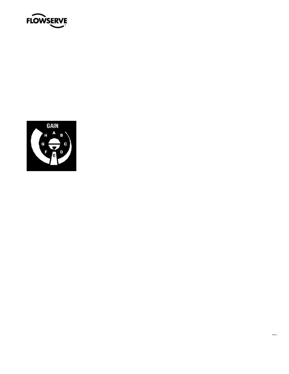
during the last RE-CAL. The GAIN switch is live, meaning the settings
can be adjusted at any time by changing the rotary switch position.
(Note that there is a small black arrow indicating the selection. The
slot in the switch is NOT the indicator.)
Figure 10: Adjustable GAIN Switch
If the adjustable GAIN selector switch is set to “E” with the auto
tune switch on, a Flowserve standard response tuning set will be
calculated and used based on response parameters measured during
the last RE-CAL.
If the adjustable GAIN selector switch is set to “F”, “G”, or “H” with
the auto tune switch on, progressively higher gain settings will be
calculated and used based on response parameters measured during
the last RE-CAL.
Off Off forces the positioner to use one of the factory preset tuning
sets determined by the adjustable GAIN selector switch. Settings “A”
through “H” are progressively higher gain predefined tuning sets. The
GAIN selector switch is live and can be adjusted at any time to modify
the tuning parameters.
NOTE: “E” is the default adjustable GAIN selector switch setting for
all actuator sizes. Raising or lowering the gain setting is a function of
the positioner/valve response to the control signal, and is not actuator
size dependent.
Stability Switch
This switch adjusts the position control algorithm of the positioner for
use with low-friction control valves or high-friction automated valves.
Low-friction Valves Placing the switch to the left optimizes the
response for low-friction, high-performance control valves. This
setting provides for optimum response times when used with most
low-friction control valves.
High-friction Valves Placing the switch to the right optimizes the
response for valves and actuators with high friction levels. This
setting slightly slows the response and will normally stop limit cycling
that can occur on high-friction valves.
7.4 Description of Cal DIP Switch Settings
The sixth DIP switch selects between two calibration options. The
function of the Cal DIP switch is described below.
NOTE: The unit must be in OOS mode before a calibration sequence
can begin.
Auto Select Auto if the valve/actuator assembly has an internal stop
in the open position. In Auto mode the positioner will fully close the
valve and register the 0% position and then open the valve to the stop
to register the 100% position when performing a self-calibration. See
detailed instructions in the next section on how to perform an auto
positioner calibration.
Jog Select Jog if the valve/actuator assembly has no physical
calibration stop in the open position. In the Jog mode the positioner
will fully close the valve for the 0% position and then wait for the user
to set the open position using the Jog buttons labeled with the up and
down arrows. See the detailed instructions in Section 7.6 on how to
perform a manual calibration using the Jog buttons.
c
DANGER: During the RE-CAL operation the valve may stroke
unexpectedly. Notify proper personnel that the valve will stroke,
and make sure the valve is properly isolated.
7.5 RE-CAL Operation
NOTE: The unit must be in OOS mode before a calibration sequence
can begin.
The RE-CAL button is used to locally initiate a calibration of the
positioner. Pressing and holding the RE-CAL button for approximately
three seconds will initiate the calibration. If the Config-Switches
option is enabled, the settings of all the configuration switches are
read and the operation of the positioner adjusted accordingly. A
RE-CAL can be aborted at any time by briefly pressing the RE-CAL
button and the previous settings will be retained.
If the Quick Calibration switch (be careful not to confuse this with the
RE-CAL button) is set to Auto and the valve/actuator assembly has
the necessary internal stops the calibration will complete automati-
cally. While the calibration is in progress you will notice a series of
different lights flashing indicating the calibration progress. When
the lights return to a sequence that starts with a green light the
calibration is complete. An explanation of the various light sequences
follows. The initial calibration of extremely large or small actuators
may require several calibration attempts. The positioner adapts to
the actuator performance and begins each calibration where the last
attempt ended. On an initial installation it is recommended that after
the first successful calibration that one more calibration be completed
for optimum performance.