Flowserve UEX Limitorque User Manual
Page 19
19
Limitorque UEX FCD LMENIM1205-03-AQ – 05/15
flowserve.com
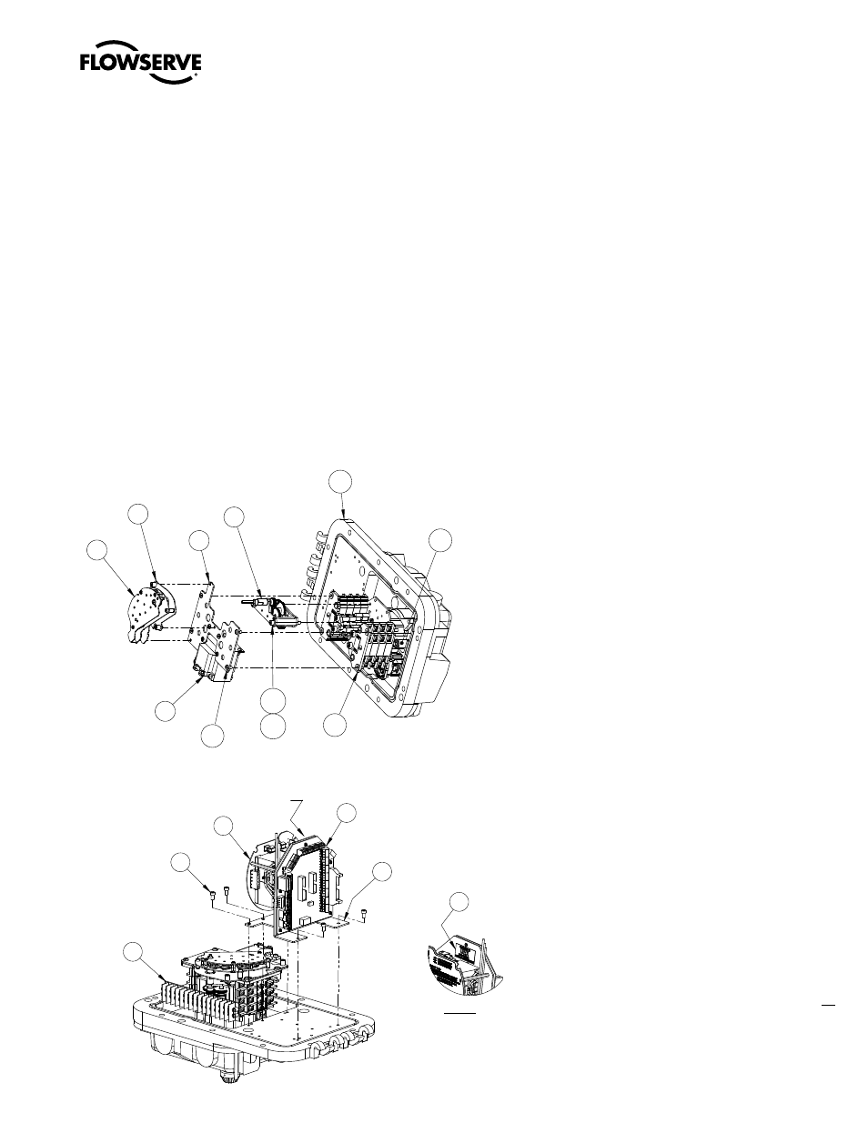
11. Connect the Encoder Board Harness (pc# 2-4) to the Main Board J-1 (pc#1-2). (See Figures 5.1 & 5.3)
12. Install the Main Board Assembly (pc# 1-2), with option boards (pc# 1-3) if supplied, using four Pan Head Screws
(pc# 1-4). (See Figure 5.3)
13. Connect the existing UEC-3 Harness to the Interface Board (pc# 3-3). (See Figure 5.2)
14. Install the O-Ring onto CSE Control Station (pc# 3-7) and slide the CSE into the Controls Compartment Cover.
15. Connect the CSE Ribbon Cable to the Interface Board (pc# 3-3). (See Figure 5.2)
16. Connect the 120V cable from the Main Board Interconnect Harness to the Terminal Strip. (See Figure 5.6)
17. Attach one UEX identification label (pc# 3-8) in between the feet of the interface board bracket (See Figure 5.2).
Attach one UEX identification label to the left of the existing unit nameplate on the gearbox.
Figure 5.1 - Encoder / MDPI / Transformer Installation
Figure 5.2 - Power / Interface Board Assembly