3 setting the jumpers – Flowserve StarPac 3 User Manual
Page 23
23
StarPac Intelligent Control System FCD VLENIM0066-05 04/14
flowserve.com
®
10.3 Setting the Jumpers
The StarPac 3 system has several jumpers that are used to configure the analog and discrete I/O. The keypad must be
removed to view or change the jumper settings.
1. Contact Relay Setting
On the lower right hand side of the electronic board assembly is a three position jumper labeled “JP4.” If the
jumper is set on the two pins furthest to the right the relay is configured to Normally-open operation. If set
on the two pins furthest to the left, the jumper configures the relay to Normally-closed operation. See Figure
7.
Figure 7: Contact Relay Jumper Settings
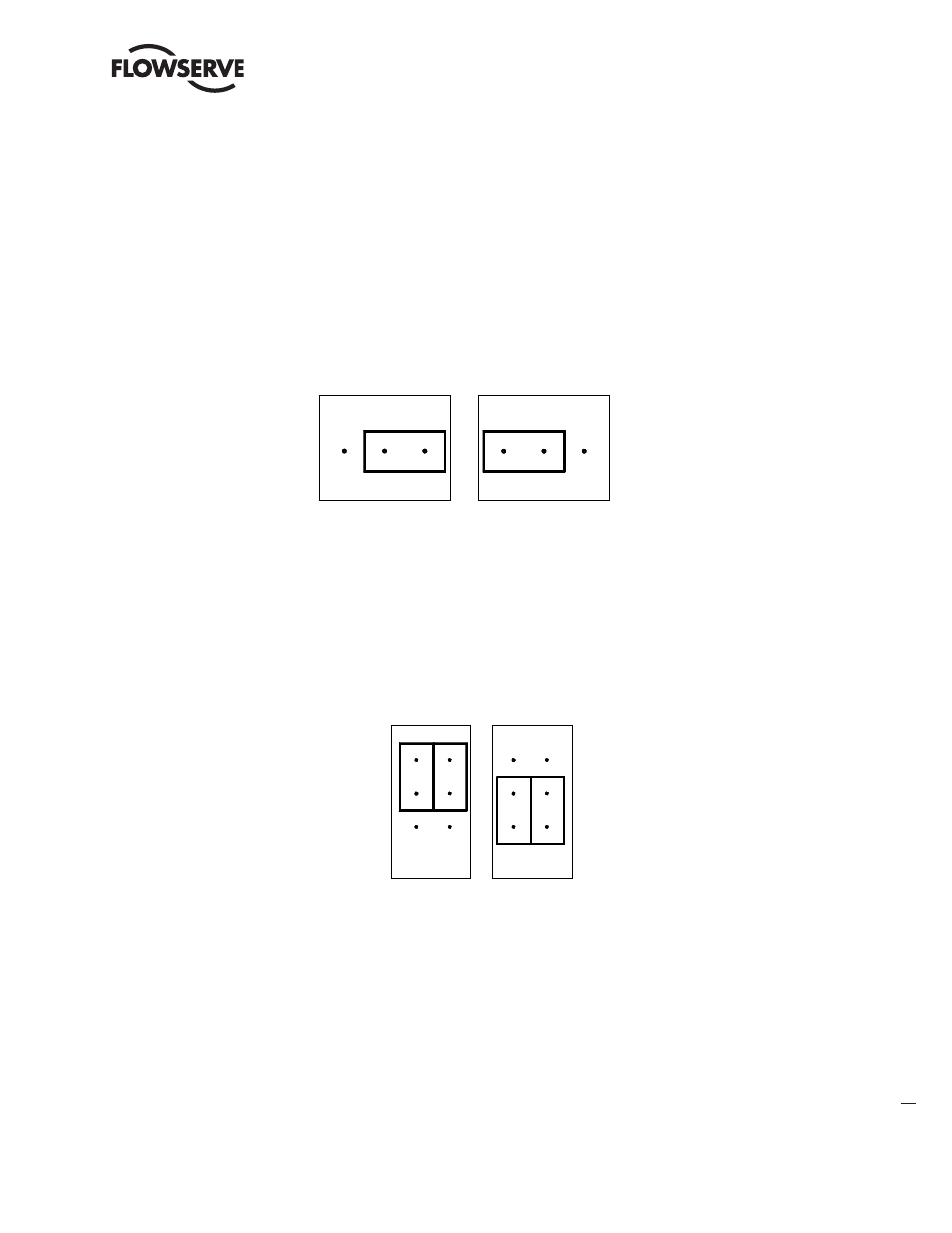
2. Discrete Input Range Selection
On the lower right hand side of the electronic board assembly is a six position jumper labeled “JP3.” There are 2 jumpers
that must be moved together to set the voltage input range. The jumpers are oriented vertically and with both jumpers
in the upper position the input is set to trigger on 120V AC or DC. With both jumpers in the lower position the input is
set to trigger on 24V AC or DC. See Figure 8.
Figure 8: Discrete Input Range Jumper Settings
3. Analog Input Power Selection
On the lower right hand side of the electronic board assembly are two, 8 position jumper arrays labeled “JP1” and “JP2.”
Each of the 4-20 mA analog inputs can be configured for either an external power supply such as exists in a DCS, or
powered internally so a transmitter or other 2 wire device can be directly connected to the terminals. JP1 configures
analog input 1 and JP2 configures analog input 2. The jumpers should be configured as shown for the desired operation.
See Figure 9.
Normally Closed
JP4
Normally Open
JP4
JP3
24 V
Setting
JP3
120 V
Setting