Flowserve StarPac 3 User Manual
Page 16
StarPac Intelligent Control System FCD VLENIM0066-05 04/14
16
®
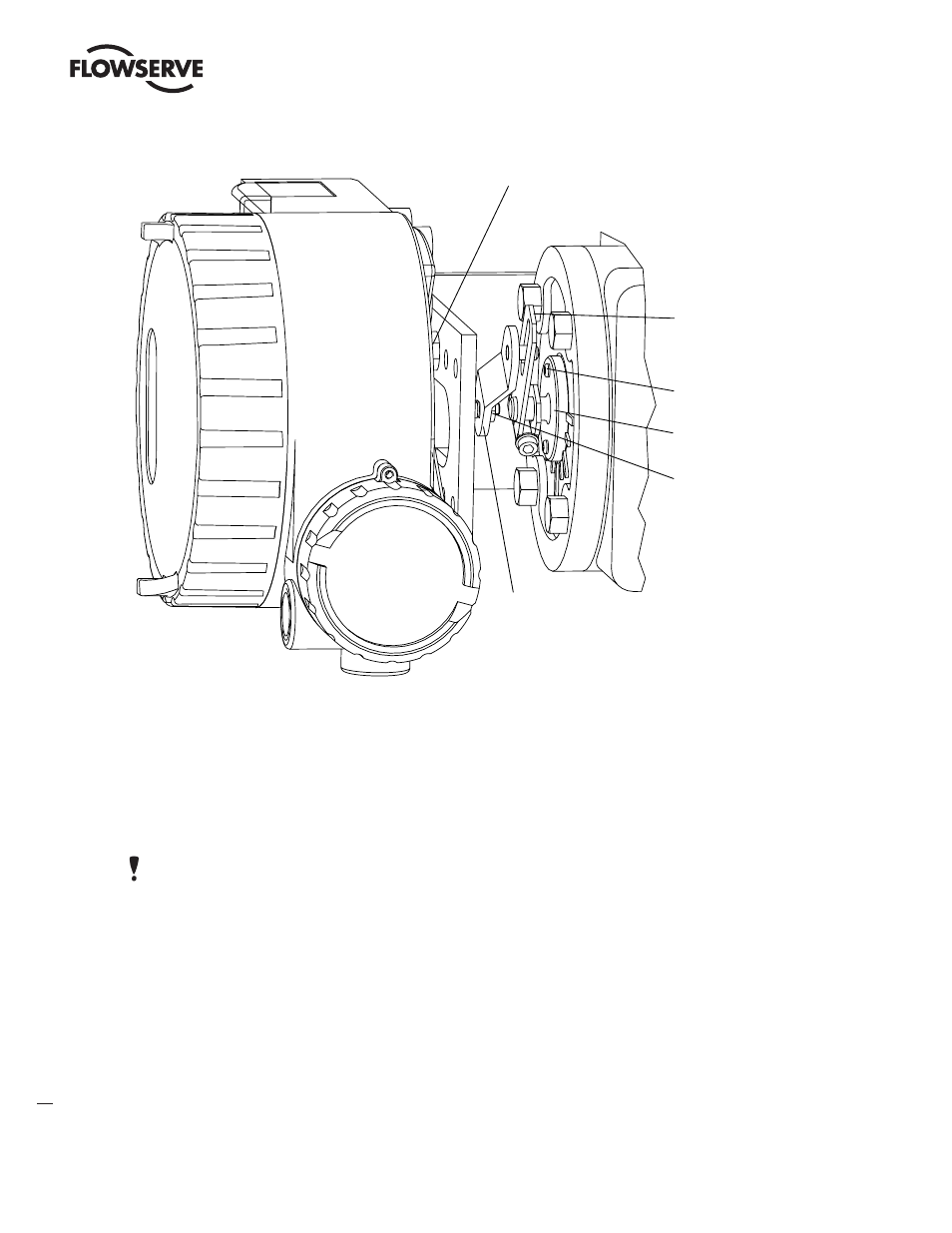
1. Fasten the splined lever adapter to the splined lever using two #4-40 x 1/2” self-tapping screws.
2. Slide the take-off arm assembly onto the splined lever adapter shaft. Insert the screw with star washer
through the take off arm and add the second star washer and nut. Tighten nut with socket so arm is lightly
snug on the shaft but still able to rotate. This will be tightened after linkage is correctly oriented.
3. Attach follower arm to positioner feedback shaft using the star washer and 10-32 nut.
NOTE: The arm will point up when feedback shaft is in the free position.
4. Using four 5/16”-18 x 5/8” bolts, fasten positioner to universal bracket using appropriate hole pattern (stam-
ped on bracket).
5. Using a 1/2” end wrench and two 5/16”-18 x 1/2” bolts, attach bracket to actuator transfer case pad. Leave
these bolts slightly loose until final adjustments are made.
6. Rotate take-off arm so the follower pin will slide into the slot on the take-off arm. Adjust the bracket position
as needed noting the engagement of the follower pin and the take-off arm slot. The pin should extend appro-
ximately 1/16” past the take-off arm. When properly adjusted, securely tighten the bracketing bolts.
7. Tube the StarPac 3 positioner to the actuator according to the instructions given in Section 8.4, “Tubing Posi-
tioner to Actuator.”
8. With supply pressure off, rotate the follower arm in the same direction the shaft would rotate upon a loss of
Figure 3: Standard Rotary Mounting (Sensor Mounting not shown)
StarPac 3
Follower Arm
*Located in appropriate
hole pattern as indicated on
bracket. (25, 50, 100/200)
Positioner Bolts 5/16-18 (4)*
Bracket Bolts 5/16-18 (2, not shown)
Take-off Arm, Rotary
Lock Washer (2)
10-32 Bolt
10-32 Nut
Self-tapping Screws (2)
Spline Lever Adapter
10-32 Nut
Lock Washer