Flowserve MF User Manual
Page 43
MF USER INSTRUCTIONS ENGLISH 71569191 12/04
Page 43 of 50
®
j) Install grease fittings, constant level oiler, and vent
cap, as applicable, and plug any remaining open
holes
6.9.2 Assembly of bearing frames 4T,5T,6A & 7A.
a) Be sure the shoulders where bearings seat are
free of burrs and contaminants.
b) If grease lubricated, be sure the grease retainers
are in place prior to installing the outer races.
Mount the outer races of these bearings (cups)
into their respective housing bores (either chill to
install or press in). Be sure the races seat
against the housing shoulders.
c) Assemble line bearing cone on shaft in the
direction shown on the sectional drawing.
Thoroughly grease this bearing (if grease
lubricated).
d) Install shaft, with the line bearing cone fitted,
through the housing and support the assembly
vertically (thrust end up).
e) If oil lubricated, install the line bearing oil thrower
(heat or press to install) in the direction shown on
the sectional drawing. Assemble the line bearing
inner seal, the line bearing cover with gasket, the
outer seal, shaft sleeve, stuffing box head,
impeller, and the impeller nut. The line bearing oil
thrower gap is not adjustable (except for the 6A
bearing frame). See note (f).
If the line bearing oil thrower rubs against the line
bearing cover at assembly, increase the gap by
doubling up on the line bearing cover gasket.
f)
The 6A bearing frame line bearing oil
thrower is adjustable. Install in a manner similar
to the thrust bearing oil thrower outlined in step
(e).
g) Heat thrust bearing cone to approximately 93 °C
(200 °F) and assemble it on the shaft together
with bearing washer, lock-washer and nut. Hand
tighten the nut. Thoroughly grease this bearing
(if grease lubricated).
h) Adjust the end play to give 0.05~0.10 mm (0.002
~0.004 in.) on a dial indicator.
i)
At this point it is suggested that the line bearing
cover and seal rings, shaft sleeve, stuffing box
head, impeller, impeller cover plate and impeller
screw be assembled. Then proceed to adjust the
end play as listed in section 6.9.3.
6.9.3 Bearing end play adjustment procedure
Grease all the seal lips before installation.
Position the outside seals (line and thrust bearing)
with minimum lip contact to the covers. Excessive lip
pressure will result in the seal running hot and
premature seal failure.
a) Mount a dial indicator on the thrust end of the
housing with its arm resting on top of the pump
shaft.
b) With the bearing assembly supported vertically by
the impeller, oscillate the frame to allow the line
bearing rollers to fully seat. If this is not done false
readings will be obtained. Record the dial
indicator reading.
c) Now lift the bearing frame and oscillate the shaft
to allow the thrust bearing rollers to fully seat.
Record the dial indicator reading.
d) The bearing end play is the difference in the
above readings. The initial end play will usually
be 0.13~0.40 mm (0.005 ~0.015 in.). Adjust the
end play by tightening the thrust bearing nut as
necessary and repeating the above procedure to
check the end play.
e) If the end play becomes less than 0.05 mm
(0.002 in.) the thrust bearing nut must be
loosened and the thrust bearing cone backed off
by pressing (due to likelihood of being an
interference fit). Then repeat the above
procedure to set the end play.
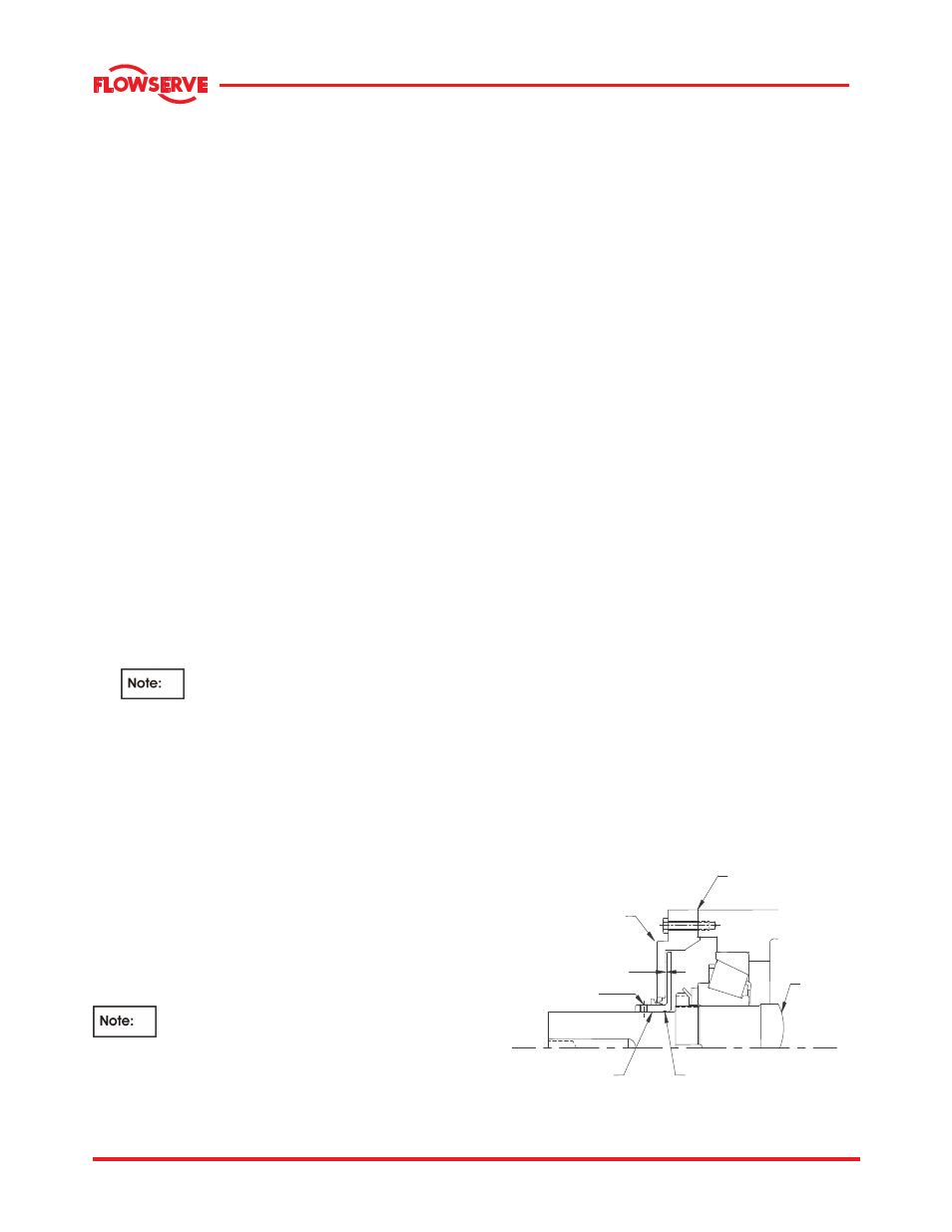
f) If oil lubricated, install the thrust bearing oil
thrower with its ‘O’ ring, inner seal and thrust
bearing cover with gasket; see section 6.9.1.1.
Adjust the gap by pulling the thrower up to the
cover and scribing a line on the pump shaft.
Then push the oil thrower in 0.76~1.3 mm (0.030
- 0.050 in.) to set the gap. Tighten the set
screws to secure the oil thrower to the shaft.
Install the outer seal.
g) Install the thrust bearing cover and seal rings.
Grease the seal ring lips and position such that
minimum lip contact to the covers occur.
Excessive lip pressure will result in the seal rings
running hot and premature ring failure.
h) Install grease fittings, oil sight glass, and vent
cap, as applicable, and plug any remaining open
holes.
6.9.1.1 Oil thrower assembled
OIL
SET
SCREW
GAP
THRUST
BEARING
COVER
O-RING
SHAFT
GASKET OR
O - RING