Flowserve MF User Manual
Page 13
MF USER INSTRUCTIONS ENGLISH 71569191 12/04
Page 13 of 50
®
3.2 Nomenclature
The pump size is engraved on the nameplate
typically as below:
16- MF- 18
Nominal discharge branch size
(in inches only)
Type: Horizontal close coupled
Nominal impeller diameter (in inches only)
Measurement shown above for discharge
branch size and impeller diameter are always
provided in inches.
The typical nomenclature above is the general guide
to the MF configuration description. Identify the
actual pump size and serial number from the pump
nameplate. Check that this agrees with the
applicable certification provided. The driver will have
separate nameplate attached to it.
3.3 Design of major parts
3.3.1 Pump casing and stuffing box head
The pump casing with its integrally cast discharge
nozzle is of the volute type. It is machined to provide
a rabbet fit for the stuffing box head and suction
head. The heads are removable and are bolted to
and centered in the casing. The casing and suction
head are each provided with one hand hole for
inspection and cleaning of the pump without
dismantling.
The pump has its main casing gasket
axial to the shaft allowing maintenance to the rotating
element by separating the impeller assembly from
the casing. Suction and discharge branches remain
undisturbed.
3.3.2 Impeller
The impeller hub is keyed to the shaft and held in
position by an impeller nut which is set screwed to
the impeller to prevent its backing off. A pair of
replaceable wearing rings (optional) between the
rotating impeller and the stationary suction head are
provided for impeller wear resistance.
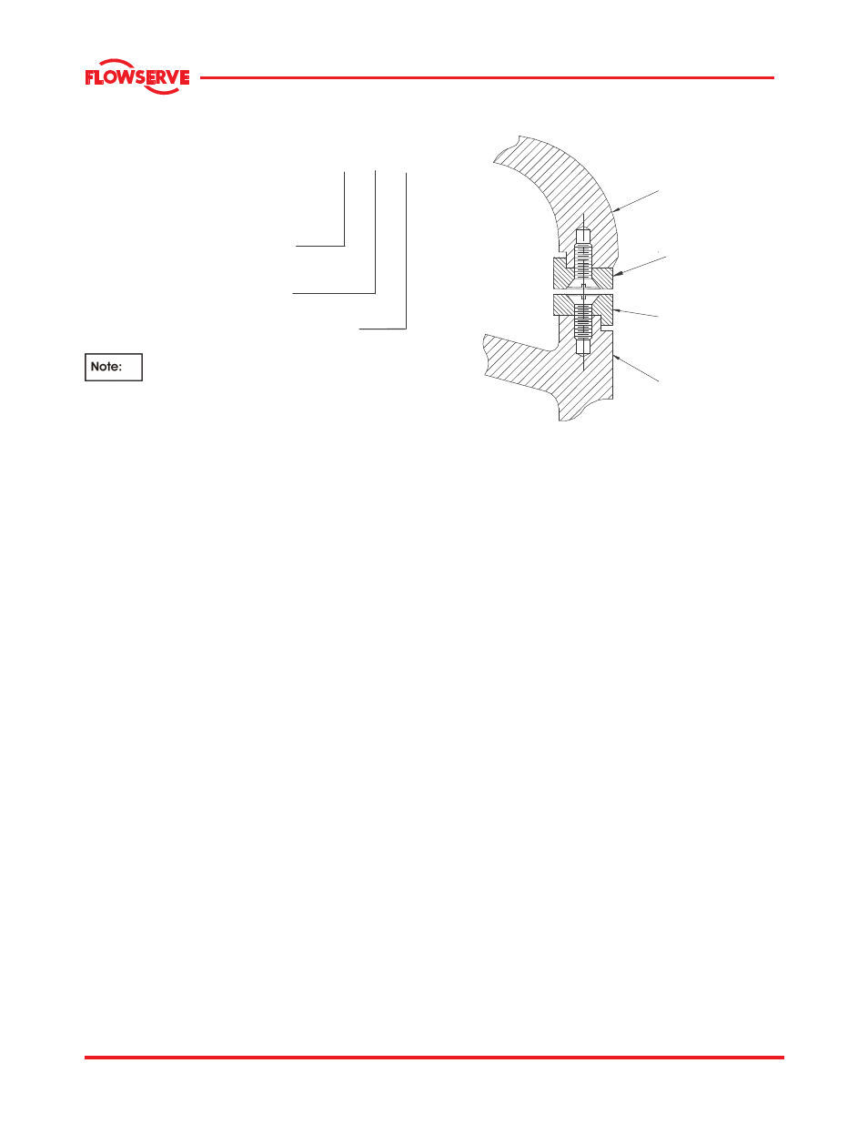
3.3.2.1 Impeller and wearing ring arrangement
IMPELLER
IMPELLER
WEARING RING
SUCTION HEAD
WEARING RING
SUCTION HEAD
3.3.3 Shaft and shaft sleeve
The pump shaft is sized to transmit the rated loads
encountered with liberal safety factors, and is
accurately machined over its full length. Generous
fillets are used to minimize stress concentrations. It
is protected from wear at the stuffing box by a
removable shaft sleeve.
3.3.4 Pump bearings
MF pumps are equipped with anti-friction bearings
(for frames 3A, 4A and 5A) and tapered roller types
(for frames 4T,5T,6A and 7A). The line and thrust
bearings are arranged in opposed mounting and can
be furnished with either grease or oil lubrication.
Bearings are grease lubricated as standard.
3.3.5 Bearing housing
Bearings are mounted in a removable cast iron
bearing frame. The frame casting offers rigid support
and location to the bearings and two grease nipples
enable grease-lubricated bearings to be replenished
between major service intervals.
3.3.6 Stuffing box housing
The stuffing box housing cast integrally with the back
head and has designed to accommodate number of
sealing options. For applications requiring
mechanical seals refer to the mechanical seal
manufacturer's User Instructions.
Packing within the pump stuffing box seals the pump
against leakage along the shaft at the point where it
passes through the stuffing box. It should be packed
with rings of braided, non-asbestos packing and a
seal cage as shown in detail under this section. It is
equipped with a removable split packing gland.