Flowserve MF User Manual
Page 41
MF USER INSTRUCTIONS ENGLISH 71569191 12/04
Page 41 of 50
®
k) Remove the shaft sleeve only if necessary. When
the shaft sleeve becomes grooved 1/8" deep at
any point, its replacement becomes necessary to
avoid future potential damage to the pump. For
removal of shaft sleeve refer to "Maintenance of
Shaft Sleeve".
l) If there is any reason to suspect a bent shaft it
should be checked for runout with a dial indicator
before dismantling the bearing frame. Maximum
shaft runout is .002" T.I.R..
m) Steps 14 through 18 pertain to disassembly of
ball bearing frames 3A, 4A and 5a. For
disassembly procedure on tapered roller bearing
frames 4T, 5T, 6A and 7A go to step (s).
n) To disassemble the bearing frame, remove the 4
cap screws that hold the thrust bearing housing
cover to the bearing housing.
o) Remove the shaft and bearings by pressing on the
impeller end of the shaft. Protect the end of the
shaft during this operation.
p) The thrust bearing cover may be pulled off the
shaft at any time. If desired the line bearing cover
may be removed by removing 4 cap screws.
q) Seal rings are removed by pressing them outward
from their respective mountings.
r) For removal of bearings refer to "Maintenance of
Bearings".
Disassembly procedure for taper roller bearing
frames 4T, 5T, 6A and 7A
s) Remove the thrust and line bearing housing
covers and their respective seal rings.
t) If oil lubricated, remove the thrust and line bearing
oil throwers by backing off the set screws and
sliding the throwers and the "O" rings off the shaft.
u) Disengage thrust bearing lock-washer tab from its
locknut. Unscrew the bearing locknut and remove
the bearing lock-washer and washer.
v) Remove shaft toward impeller end. The thrust
bearing will be pushed off the shaft by this
movement. Do not remove grease retainers
unless for replacement.
w)
For further removal of bearings refer to
"Maintenance of Bearings".
As the pump and rotor is dismantled, all individual
parts, all important joints and all wearing surfaces
should be carefully examined. As a general rule,
regardless of the performance of the unit, parts
appreciably worn should be renewed if it is not
intended to examine the pump until the next overhaul
period.
6.7.3 Bearing installation and removal
Anti-friction bearing cones (inner race) are usually
pressed or shrunk onto the shaft. The cups (outer
races) are usually pressed or shrunk into the bearing
housing. When mounting bearings it is important that
the proper fit is maintained.
When a pulling device is used to remove bearings
from the shaft, the pulling jaws or fingers should be
located on the bearing cone. When other parts do
not interfere, the bearing cone may be supported by
a split ring and the shaft pressed out using an arbor
press. The bearing cups can similarly be pulled out
of the housing.
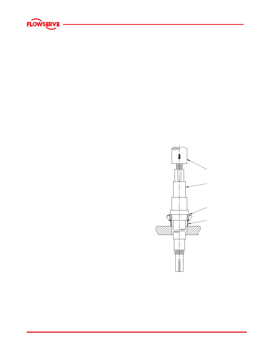
There are two methods for mounting a bearing on the
pump shaft:
a) Heating the bearing to expand the cone and
shrinking it on the shaft.
b) Pressing the bearing onto the shaft.
The method (a) is preferred over the method (b).
ARBOR PRESS
SHAFT
BEARING CONE
RING ON
CONE ONLY
Heat the bearing in an oil bath or electric oven to a
uniform temperature of 120
o
C (250
o
F). When
heated, quickly mount it on the shaft. If the alternate
method is used, apply force by means of an arbor
press; see detail below. Use a tubular sleeve, ring,
or small blocks of equal thickness to apply the force
to the cone (inner race). In forcing a bearing onto a
shaft, be careful that the cone is never cocked.